1.CHECK ANY OTHER DTC ON DISPLAY.
|
Is any other DTC displayed?
|
Check DTC using “List of Diagnostic Trouble Code (DTC)”. 
|
|
2.CHECK CURRENT DATA.
2) Read data of intake manifold absolute pressure signal using Subaru Select Monitor or general scan tool.
NOTE:
• Subaru Select Monitor
For detailed operation procedure, refer to “READ CURRENT DATA FOR ENGINE”.
• General scan tool
For detailed operation procedures, refer to the “General Scan Tool Instruction Manual”.
|
Is the measured value more than 53.3 kPa (400 mmHg, 15.75 inHg) ?
|
Make sure that the EGR valve, manifold absolute pressure sensor and throttle body are installed securely.
|
|
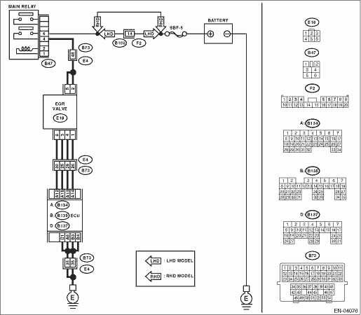
3.CHECK POWER SUPPLY OF EGR SOLENOID VALVE.
1) Disconnect the connector from EGR solenoid valve.
2) Turn the ignition switch to ON.
3) Measure the voltage between EGR solenoid valve and engine ground.
Connector & terminal
(E18) No. 2 — Engine ground:
(E18) No. 5 — Engine ground:
|
Is the voltage more than 10 V?
|
|
Repair the open circuit of harness between main relay and EGR solenoid valve connector.
|
4.CHECK EGR SOLENOID VALVE.
Measure the resistance between EGR solenoid valve terminals.
NOTE:
Make sure there is no foreign material between EGR solenoid valve and valve seat.
|
Is the resistance between 20 — 30 Ω?
|
|
Replace the EGR valve.
|
5.OUTPUT SIGNAL FROM ECM.
1) Turn the ignition switch to OFF.
2) Connect the connector to ECM and EGR solenoid valve.
3) Turn the ignition switch to ON.
4) Measure the voltage between ECM and chassis ground.
Connector & terminal
(B134) No. 12 (+) — Chassis ground (−):
(B134) No. 13 (+) — Chassis ground (−):
(B134) No. 14 (+) — Chassis ground (−):
(B134) No. 15 (+) — Chassis ground (−):
|
|
Repair the poor contact portion of ECM connector.
|
|
6.CHECK HARNESS BETWEEN EGR SOLENOID VALVE AND ECM CONNECTOR.
1) Turn the ignition switch to OFF.
2) Disconnect the connector from EGR solenoid valve and ECM.
3) Measure the resistance of harness between EGR solenoid valve and ECM connector.
Connector & terminal
(B134) No. 12 — (E18) No. 6:
(B134) No. 14 — (E18) No. 1:
(B134) No. 13 — (E18) No. 4:
(B134) No. 15 — (E18) No. 3:
|
Is the resistance less than 1 Ω?
|
|
Repair the open circuit of harness between ECM and EGR solenoid valve connector.
|
7.CHECK HARNESS BETWEEN EGR SOLENOID VALVE AND ECM CONNECTOR.
Measure the resistance of harness between EGR solenoid valve and chassis ground.
Connector & terminal
(B134) No. 12 — Chassis ground:
(B134) No. 13 — Chassis ground:
(B134) No. 14 — Chassis ground:
(B134) No. 15 — Chassis ground:
|
Is the resistance more than 1 MΩ?
|
|
Repair the short circuit of harness between main relay and EGR solenoid valve connector.
|
8.CHECK POOR CONTACT.
Check poor contact of ECM and EGR solenoid valve connectors.
|
Is there poor contact in ECM and EGR solenoid valve connectors?
|
Repair the poor contact of ECM and EGR solenoid valve connectors.
|
Even if the malfunction indicator light illuminates, the circuit has returned to the specified condition at this time.
|