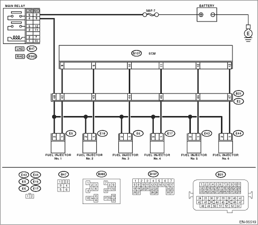
1.CHECK OUTPUT SIGNAL OF ECM.
1) Turn the ignition switch to ON.
2) Measure the voltage between the ECM and chassis ground for faulty cylinders.
Connector & terminal
#1 (B137) No. 8 (+) — Chassis ground (−):
#2 (B137) No. 9 (+) — Chassis ground (−):
#3 (B137) No. 10 (+) — Chassis ground (−):
#4 (B137) No. 11 (+) — Chassis ground (−):
#5 (B137) No. 12 (+) — Chassis ground (−):
#6 (B137) No. 13 (+) — Chassis ground (−):
|
Is the voltage 10 V or more?
|
|
|
2.CHECK HARNESS BETWEEN ECM AND FUEL INJECTOR.
1) Turn the ignition switch to OFF.
2) Disconnect the connector from fuel injector on faulty cylinders.
3) Measure the resistance between the fuel injector connector and engine ground on faulty cylinders.
Connector & terminal
#1 (E5) No. 1 — Engine ground:
#2 (E16) No. 1 — Engine ground:
#3 (E6) No. 1 — Engine ground:
#4 (E17) No. 1 — Engine ground:
#5 (E43) No. 1 — Engine ground:
#6 (E44) No. 1 — Engine ground:
|
Is the resistance 1 MΩ or more?
|
|
Repair the ground short circuit of harness between ECM and fuel injector.
|
3.CHECK HARNESS BETWEEN ECM AND FUEL INJECTOR.
Measure the resistance of harness between the ECM and fuel injector on faulty cylinders.
Connector & terminal
#1 (B137) No. 8 — (E5) No. 1:
#2 (B137) No. 9 — (E16) No. 1:
#3 (B137) No. 10 — (E6) No. 1:
#4 (B137) No. 11 — (E17) No. 1:
#5 (B137) No. 12 — (E43) No. 1:
#6 (B137) No. 13 — (E44) No. 1:
|
Is the resistance less than 1 Ω?
|
|
Repair the harness and connector.
NOTE:
In this case, repair the following item:
• Open circuit of harness between ECM and fuel injector connector
• Poor contact of coupling connector
|
4.CHECK FUEL INJECTOR.
Measure the resistance between fuel injector terminals on faulty cylinder.
|
Is the resistance between 5 — 20 Ω?
|
|
Replace the faulty fuel injector. 
|
5.CHECK POWER SUPPLY LINE.
1) Turn the ignition switch to ON.
2) Measure the voltage between fuel injector and engine ground on faulty cylinders.
Connector & terminal
#1 (E5) No. 2 (+) — Engine ground (−):
#2 (E16) No. 2 (+) — Engine ground (−):
#3 (E6) No. 2 (+) — Engine ground (−):
#4 (E17) No. 2 (+) — Engine ground (−):
#5 (E43) No. 2 (+) — Engine ground (−):
#6 (E44) No. 2 (+) — Engine ground (−):
|
Is the voltage 10 V or more?
|
Repair the poor contact of all connectors in fuel injector circuit.
|
Repair the harness and connector.
NOTE:
In this case, repair the following item:
• Open circuit of harness between main relay and fuel injector on faulty cylinders
• Poor contact of coupling connector
• Poor contact of main relay connector
• Poor contact of fuel injector connector on faulty cylinders
|
6.CHECK HARNESS BETWEEN ECM AND FUEL INJECTOR.
1) Turn the ignition switch to OFF.
2) Disconnect the connector from fuel injector on faulty cylinders.
3) Turn the ignition switch to ON.
4) Measure the voltage between the ECM and chassis ground for faulty cylinders.
Connector & terminal
#1 (B137) No. 8 (+) — Chassis ground (−):
#2 (B137) No. 9 (+) — Chassis ground (−):
#3 (B137) No. 10 (+) — Chassis ground (−):
#4 (B137) No. 11 (+) — Chassis ground (−):
#5 (B137) No. 12 (+) — Chassis ground (−):
#6 (B137) No. 13 (+) — Chassis ground (−):
|
Is the voltage 10 V or more?
|
Repair the short circuit to power in the harness between the ECM and fuel injector.
|
|
7.CHECK FUEL INJECTOR.
1) Turn the ignition switch to OFF.
2) Measure the resistance between fuel injector terminals on faulty cylinder.
|
Is the resistance less than 1 Ω?
|
Replace the faulty fuel injector.
|
|
8.CHECK INSTALLATION OF CAMSHAFT POSITION SENSOR/CRANKSHAFT POSITION SENSOR.
|
Is the camshaft position sensor or crankshaft position sensor loosely installed?
|
Tighten the camshaft position sensor or crankshaft position sensor.
|
|
|
|
Is the crank sprocket rusted or the teeth of crank plate broken?
|
Replace the crank plate.
|
|
10.CHECK INSTALLATION CONDITION OF TIMING CHAIN.
Turn the crankshaft using ST, and align alignment mark on crank sprocket with alignment mark on cylinder block.
| ST 18252AA000 |
CRANKSHAFT SOCKET |
|
Is the timing chain dislocated from its proper position?
|
Correct the installation condition of timing chain.
|
|
|
|
Is the fuel meter indication lower than the “Lower” level?
|
Replenish fuel so that fuel meter indication is higher than the “Lower” level. After replenishing fuel,
|
|
12.CHECK STATUS OF MALFUNCTION INDICATOR LIGHT.
1) Clear the memory using the Subaru Select Monitor or general scan tool.
NOTE:
• Subaru Select Monitor
For detailed procedures, refer to “READ CURRENT DATA FOR ENGINE”.
• General scan tool
Refer to the general scan tool operation manual.
2) Start the engine, and drive the vehicle 10 minutes or more.
|
Does the malfunction indicator light illuminate or blink?
|
|
|
13.CHECK CAUSE OF MISFIRE.
|
Has the cause of misfire been detected while running the engine?
|
Finish diagnostics operation, if the engine has no abnormality.
|
Repair the poor contact of connector.
NOTE:
In this case, repair the following item:
• Poor contact of ignition coil connector
• Poor contact of fuel injector connector on faulty cylinders
• Poor contact in ECM connector
• Poor contact of coupling connector
|
14.CHECK AIR INTAKE SYSTEM.
|
Is there any fault in air intake system?
|
Repair the air intake system.
NOTE:
Check the following items.
• Are there air leaks or air suction caused by loose or dislocated nuts and bolts?
• Are there cracks or any disconnection of hoses?
|
|
15.CHECK MISFIRE SYMPTOM.
1) Turn the ignition switch to ON.
2) Read the DTC.
NOTE:
• Subaru Select Monitor
For detailed operation procedures, refer to “READ CURRENT DATA FOR ENGINE”.
• General scan tool
For detailed operation procedures, refer to the general scan tool operation manual.
|
Does the Subaru Select Monitor or general scan tool indicate only one DTC?
|
|
|
16.CHECK ANY OTHER DTC ON DISPLAY.
|
Are DTCs P0301 and P0302 displayed?
|
|
|
|
|
Are DTCs P0303 and P0304 displayed?
|
|
|
|
|
Are DTC P0305 and P0306 displayed?
|
|
|
|
|
Are DTC P0301, P0303 and P0305 displayed?
|
|
|
|
|
Are DTC P0302, P0304 and P0306 displayed?
|
|
|
|
|
Is there any fault in the cylinder?
|
Repair or replace faulty parts.
NOTE:
Check the following items.
• Spark plug
• Fuel injector
• Compression ratio
|
Check DTC P0171, P0172, P0174 or P0175 using “List of Diagnostic Trouble Code (DTC)”.
|
22.GROUP OF #1 AND #2 CYLINDERS.
|
Are there any faults in #1 and #2 cylinders?
|
Repair or replace faulty parts.
NOTE:
• Check the following items.
• Spark plug
• Fuel injector
• Ignition coil
• Compression ratio
• If any fault are not found, check the “IGNITION CONTROL SYSTEM” of #1 and #2 cylinders side.
|
Check DTC P0171, P0172, P0174 or P0175 using “List of Diagnostic Trouble Code (DTC)”.
|
23.GROUP OF #3 AND #4 CYLINDERS.
|
Are there any faults in #3 and #4 cylinders?
|
Repair or replace faulty parts.
NOTE:
• Check the following items.
• Spark plug
• Fuel injector
• Ignition coil
• Compression ratio
• If any fault are not found, check the “IGNITION CONTROL SYSTEM” of #3 and #4 cylinders side.
|
Check DTC P0171, P0172, P0174 or P0175 using “List of Diagnostic Trouble Code (DTC)”.
|
24.GROUP OF #5 AND #6 CYLINDERS.
|
Are there any faults in #5 and #6 cylinders?
|
Repair or replace faulty parts.
NOTE:
• Check the following items.
• Spark plug
• Fuel injector
• Ignition coil
• Compression ratio
• If any fault are not found, check the “IGNITION CONTROL SYSTEM” of #5 and #6 cylinders side.
|
Check DTC P0171, P0172, P0174 or P0175 using “List of Diagnostic Trouble Code (DTC)”.
|
25.GROUP OF #1, #3 AND #5 CYLINDERS.
|
Is there any fault in #1, #3 and #5 cylinders?
|
Repair or replace faulty parts.
NOTE:
Check the following items.
• Spark plug
• Fuel injector
• Compression ratio
• Skipping timing chain teeth
|
Check DTC P0171, P0172, P0174 or P0175 using “List of Diagnostic Trouble Code (DTC)”.
|
26.GROUP OF #2, #4 AND #6 CYLINDERS.
|
Is there any fault in #2, #4 and #6 cylinders?
|
Repair or replace faulty parts.
NOTE:
Check the following items.
• Spark plug
• Fuel injector
• Compression ratio
• Skipping timing chain teeth
|
Check DTC P0171, P0172, P0174 or P0175 using “List of Diagnostic Trouble Code (DTC)”.
|
|
|
Is the engine idle rough?
|
Check DTC P0171, P0172, P0174 or P0175 using “List of Diagnostic Trouble Code (DTC)”.
|
Repair or replace faulty parts.
NOTE:
Check the following items.
• Spark plug
• Fuel injector
• Compression ratio
|