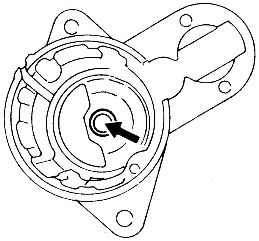
Starting Motor Inspection
Precautions: General safety (00)
Starting Motor Operation Check
 CAUTION:
Sparks resulting from a short circuit between the positive (+) and negative (–) terminals during connections to the battery may cause burns.
Be careful not to short-circuit the positive (+) and negative (–) cables, and connect them only to the correct terminals.
NOTICE:
If battery power is applied too long in any of the following tests, coil of the magnetic switch may burn.
Each test must be completed within 3 to 5 seconds to avoid burning of the coil.
1)Perform pull-in test as follows.
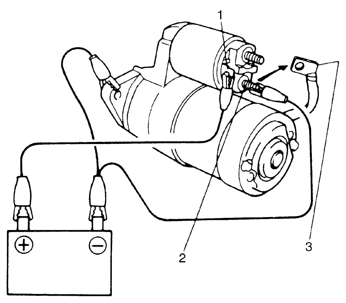

a)Disconnect lead wire (3) from terminal “M” (2).
b)Connect battery to magnetic switch as shown in figure.
c)Check that plunger and pinion move outward.
If plunger and pinion do not move, replace magnetic switch.
If plunger and pinion do not move, replace magnetic switch.
| 1. | Terminal “S” |
2)Perform hold-in test as follows.
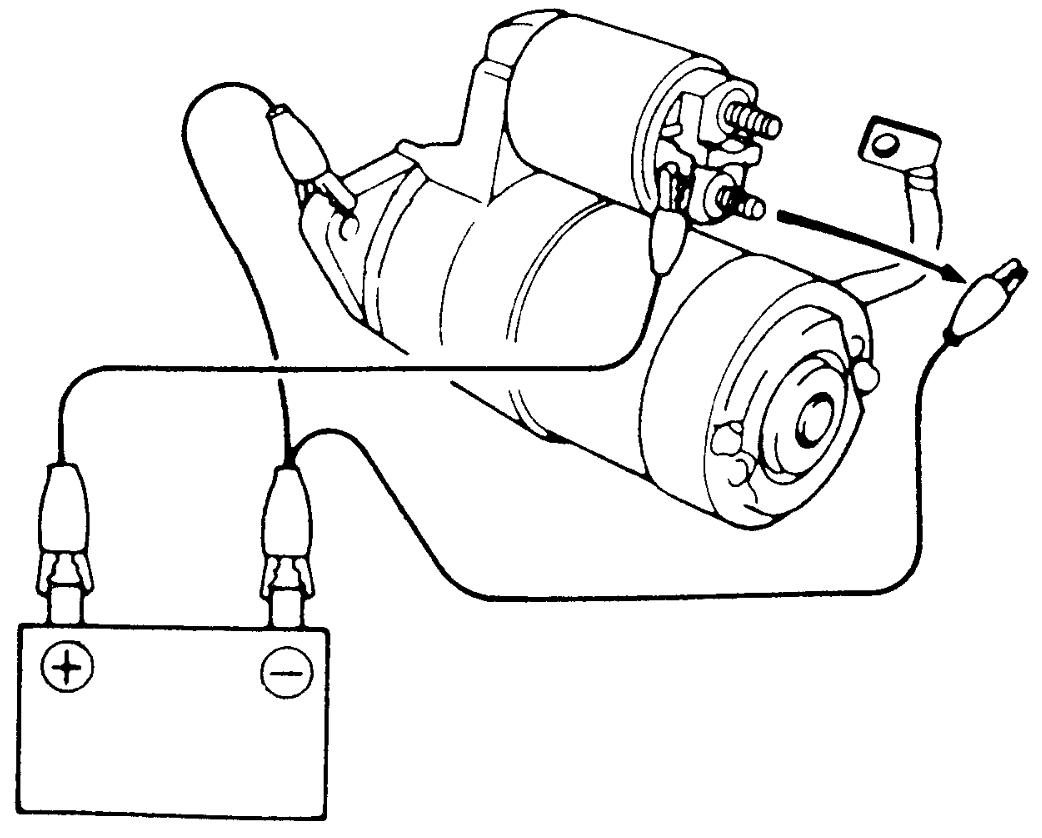
a)From the state of Step 1) with plunger and pinion in “out” position, disconnect negative (–) lead from terminal “M”.
b)Check that plunger and pinion remain in “out” position.
If plunger and pinion return inward, replace magnetic switch.
If plunger and pinion return inward, replace magnetic switch.
3)Perform plunger and pinion return test as follows.
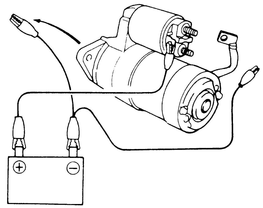
a)From the state of Step 2) with plunger and pinion in “out” position, disconnect negative (–) lead from starting motor body.
b)Check that plunger and pinion return inward.
If plunger and pinion do not return, replace magnetic switch.
If plunger and pinion do not return, replace magnetic switch.
4)Perform no-load performance test as follows.
CAUTION:
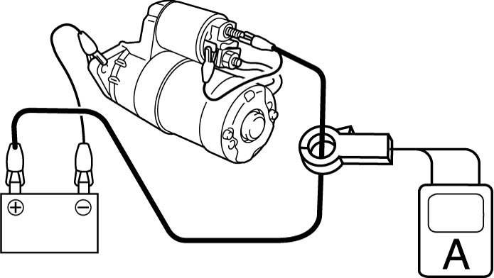
CAUTION:
If the cable used for the test is not adequately thick, the cable may become extremely hot due to large current flowing through it and you could get burned.
Use a cable with thickness equal to or larger than the cable used between the vehicle’s battery and the starter.
a)Fix starting motor with vice or the like.
b)Connect battery and ammeter to starting motor as shown in figure.
c)Check that starting motor rotates smoothly and steadily with pinion moving out.
d)Check that ammeter indicates specified current.
If check result is not as specified, repair or replace starting motor.
If check result is not as specified, repair or replace starting motor.
Specified current (No-load performance test)
Non-ENG A-STOP model: 95 A MAX. at 11 V
ENG A-STOP model: 90 A MAX. at 11 V
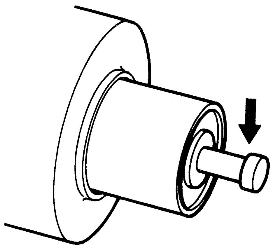
Plunger (Non-ENG A-STOP Model)
Check plunger for wear. Replace magnetic switch, if defective.
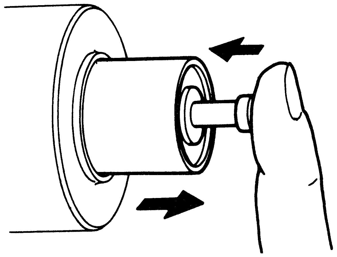
Magnetic Switch (Non-ENG A-STOP Model)
Check that plunger quickly returns to its original position when plunger is pushed in with a finger and released. If check result is not OK, replace magnetic switch.
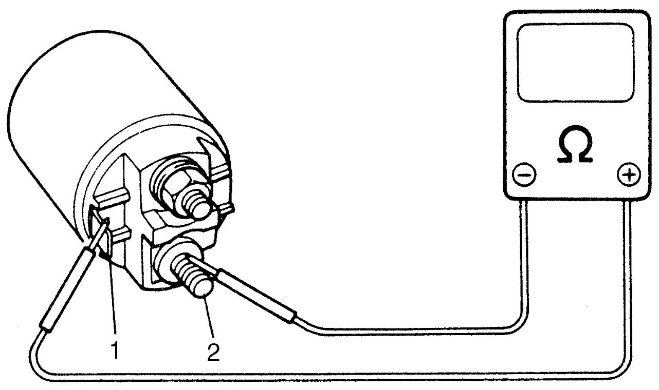
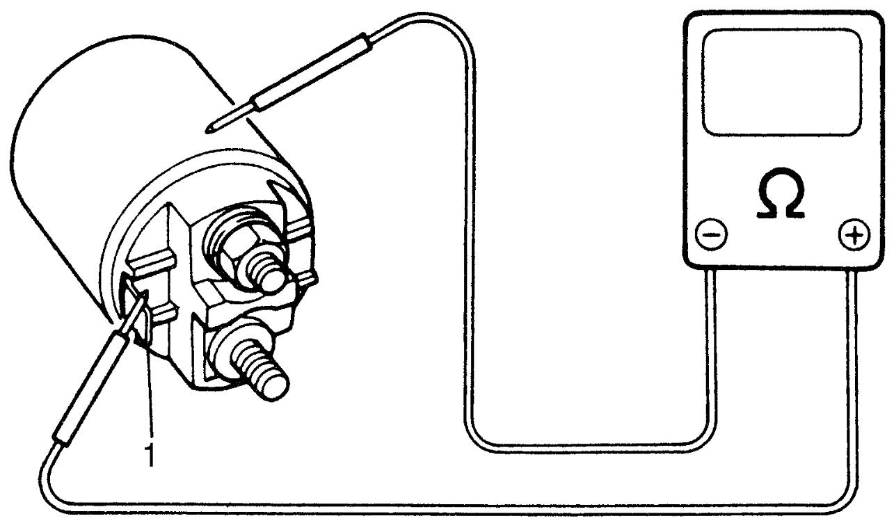
Pull-in coil open circuit test (Non-ENG A-STOP model)
Check for continuity between magnetic switch “S” terminal (1) and “M” terminal (2). If there is no continuity, replace magnetic switch.
Hold-in coil open circuit test (Non-ENG A-STOP model)
Check for continuity between magnetic switch “S” terminal (1) and coil case. If there is no continuity, replace magnetic switch.
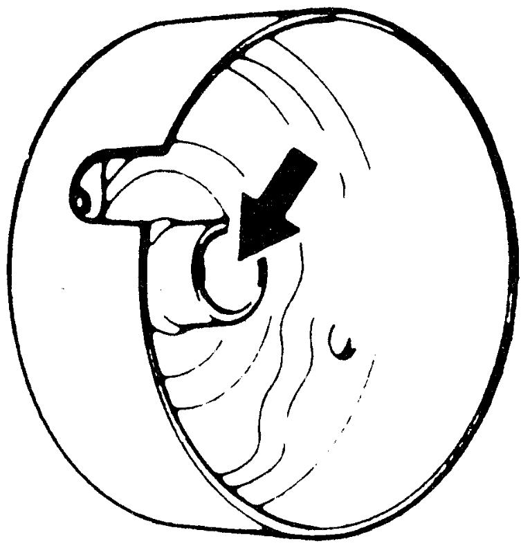
End Housing Bushing (Non-ENG A-STOP Model)
Check end housing bushing for wear or damage. Replace bushing if defective.
Brush (Non-ENG A-STOP Model)
•Check brushes for wear.
Measure length of each brush. If length is less than the limit, replace brush assembly.
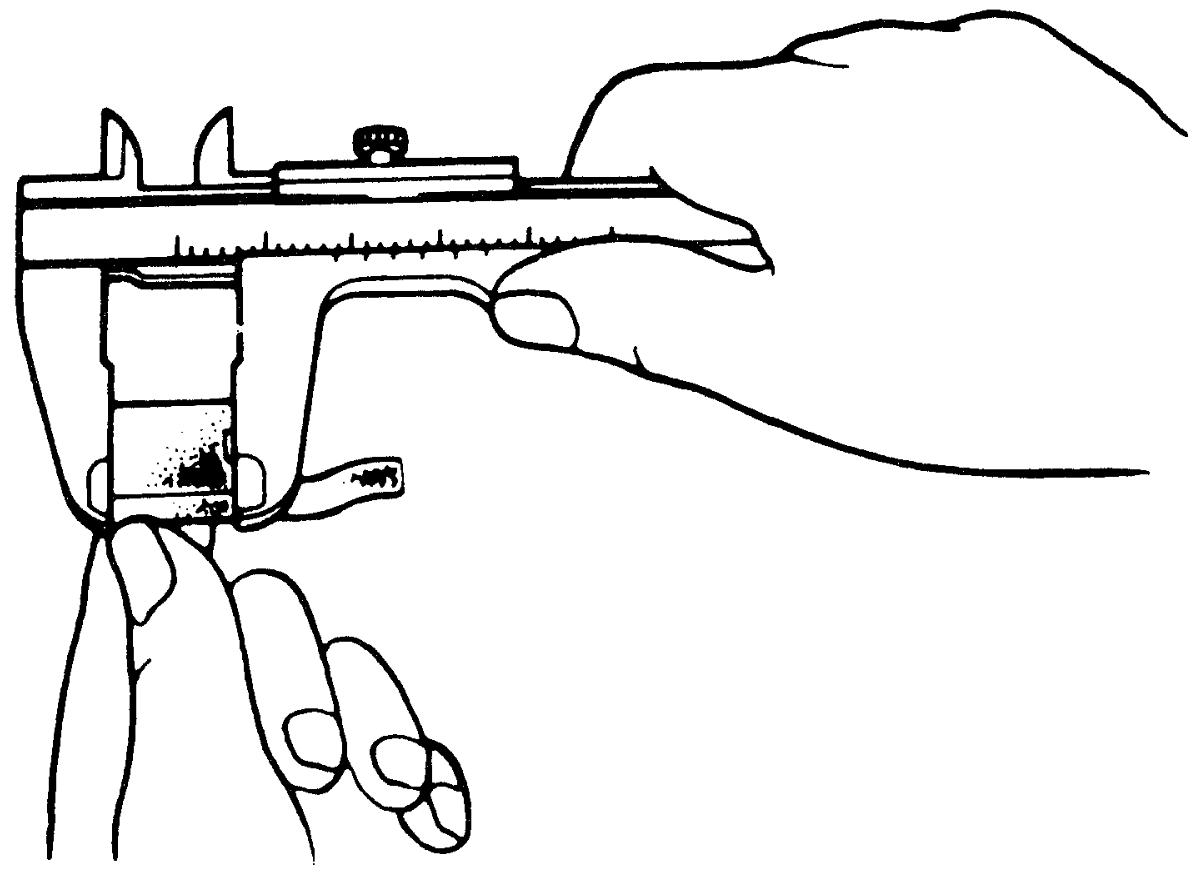 •After installing brushes into their holders, check that movement of brushes is smooth.
Measure length of each brush. If length is less than the limit, replace brush assembly.
Brush length
Standard: 12.3 mm (0.48 in.)
Limit: 5.5 mm (0.22 in.)
Spring (Non-ENG A-STOP Model)
Check brush springs for wear, damage or other abnormal conditions. Replace brush assembly if defective.
Brush spring tension
Standard: 15.0 – 20.4 N (1.6 – 2.0 kgf, 3.5 – 4.5 lbf)
Limit: 2.8 N (0.29 kgf, 0.62 lbf)
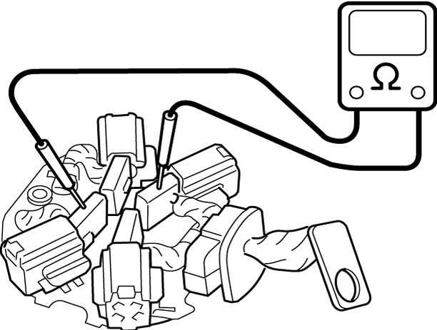
Brush Holder (Non-ENG A-STOP Model)
•Check brush holder for brush movement problems, distortion, and dirt on sliding surface.
Clean or correct brush holder if defective.
•Check for continuity between insulated brush (positive (+) side) and grounded brush (negative (–) side).
If there is continuity, replace brush holder.
Clean or correct brush holder if defective.
•Check for continuity between insulated brush (positive (+) side) and grounded brush (negative (–) side).
If there is continuity, replace brush holder.
Armature (Non-ENG A-STOP Model)
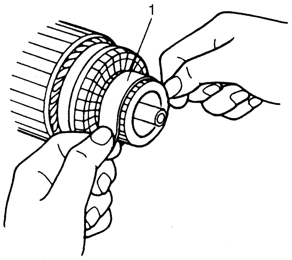
•Check commutator for dirt or burn. Correct commutator with sandpaper or lathe, if defective.
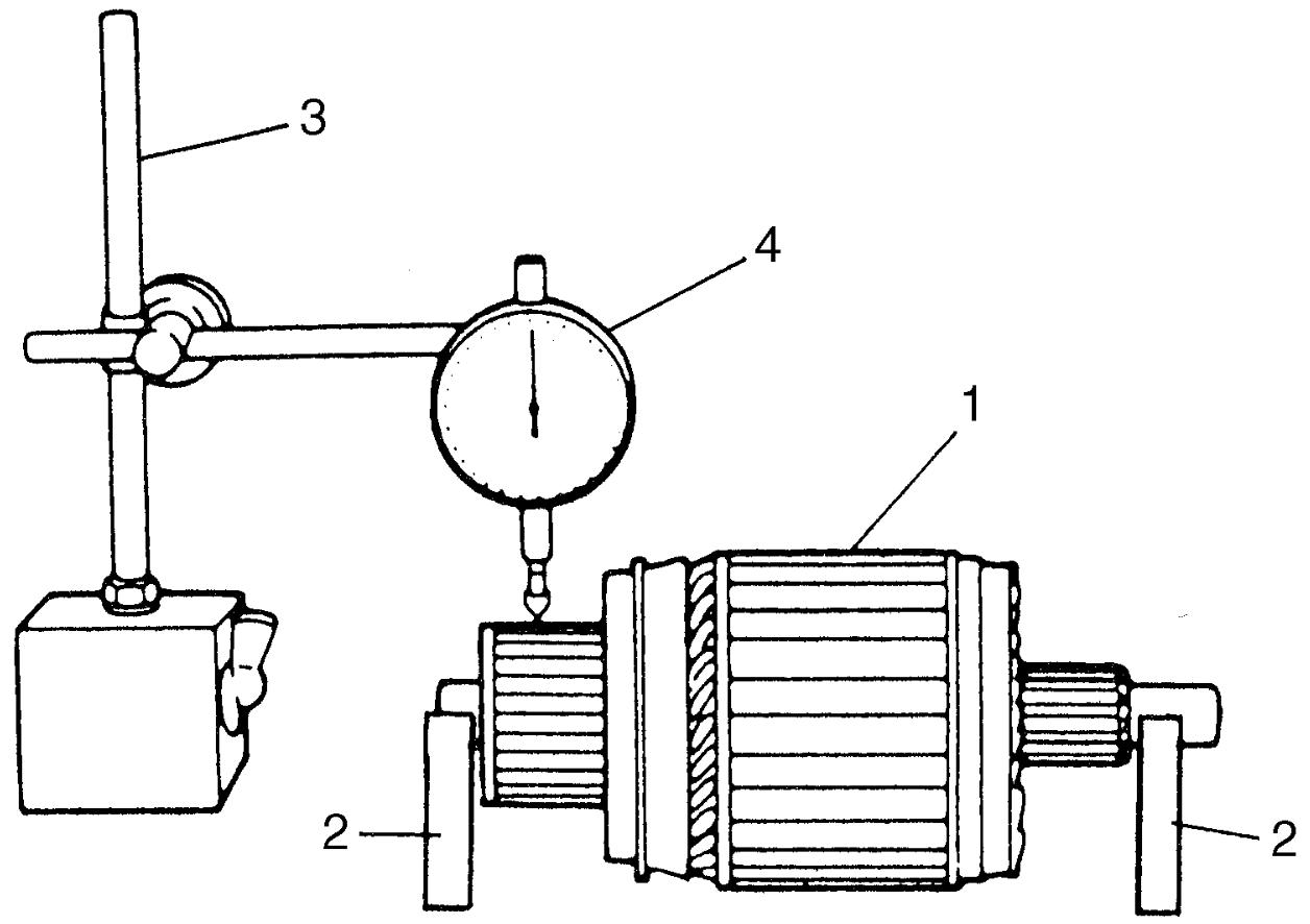
•Check commutator for uneven wear with armature (1) supported on V-blocks (2) using dial gauge (4). If dial gauge (4) deflection exceeds the limit, repair commutator or replace armature.
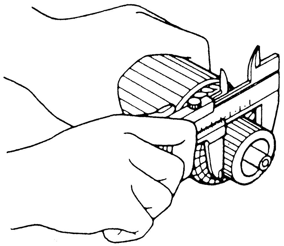
•Check commutator for wear and measure diameter of commutator. If diameter of commutator is lower than the limit, replace armature.
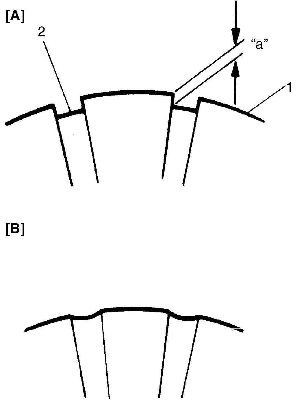
 •Check commutator (1) for insulator (2) depth. Correct insulator depth if it is smaller than limit.
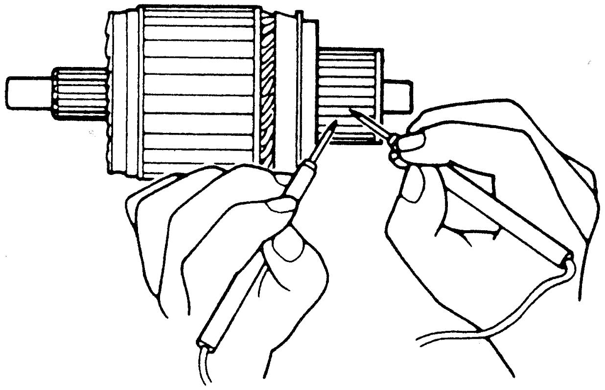
•Check insulation between commutator and armature core. If there is continuity, replace armature.
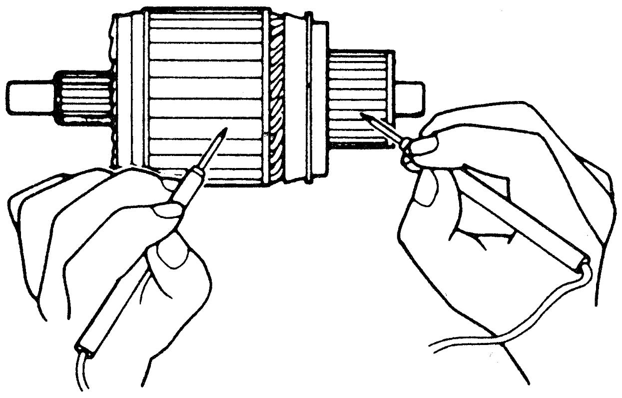 •Check for continuity between segments. If there is no continuity at any test point, replace armature.
| 1. | Sandpaper of #300 – 400 |
Commutator out of round
Standard: 0.05 mm (0.002 in.) or less
Limit: 0.4 mm (0.016 in.)
| 3. | Magnetic stand |
Commutator outside diameter
Standard: 29.4 mm (1.16 in.)
Limit: 28.8 mm (1.14 in.)
Commutator insulator depth “a”
Standard: 0.5 mm (0.019 in.)
Limit: 0.2 mm (0.008 in.)
| [A]: | Correct | [B]: | Incorrect |
Gear (Non-ENG A-STOP Model)
Check internal gear and planetary gears for wear, damage or other abnormal conditions. Replace gear set if defective.
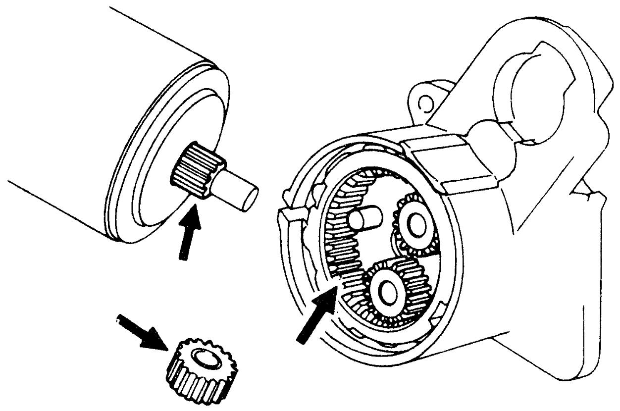
Pinion and Overrunning Clutch (Non-ENG A-STOP Model)
•Check pinion for wear, damage or other abnormal conditions.
•Check that clutch locks when turned in normal rotation direction and rotates freely when turned in reverse direction. Replace pinion and overrunning clutch if defective.
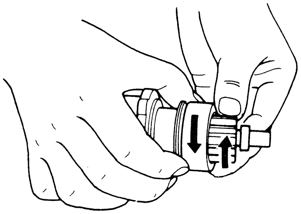 •Check spline teeth for wear or damage. If check result is not OK, replace pinion and overrunning clutch.
•Check pinion for smooth movement.
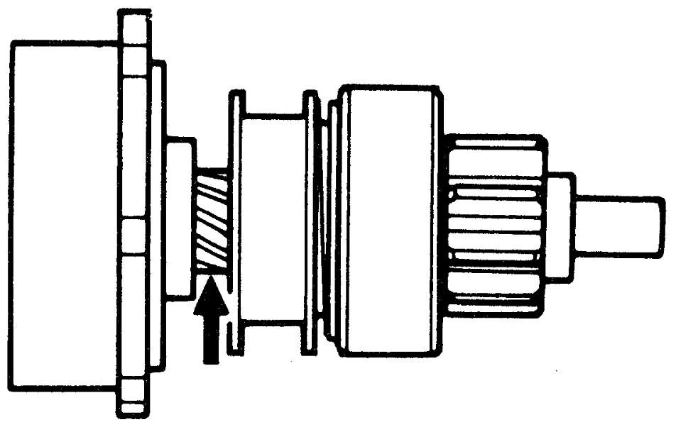
•Check that clutch locks when turned in normal rotation direction and rotates freely when turned in reverse direction. Replace pinion and overrunning clutch if defective.
•Check pinion for smooth movement.
Armature Housing Bushing (Non-ENG A-STOP Model)
Check bushing for wear and damage. Replace bushing if defective.