Cranking System Circuit Diagram
Precautions: General safety (00)
Ignition switch model
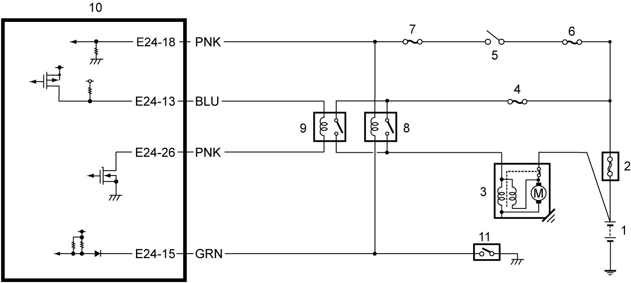
| 1. | Battery | 5. | Ignition switch | 9. | ST2 relay |
| 2. | Main fuse box | 6. | “IG2” fuse | 10. | ENG A-STOP control module |
| 3. | Starting motor | 7. | “ST SIG” fuse | 11. | CPP No.1 switch |
| 4. | “ST” fuse | 8. | Starting motor control relay |
Keyless push start and non-ENG A-STOP model
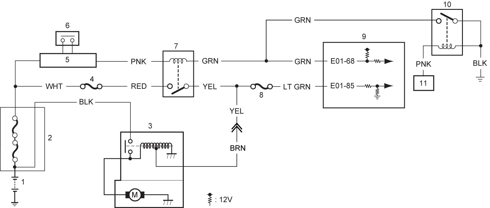
| 1. | Battery | 5. | Keyless start control module | 9. | ECM |
| 2. | Main fuse box | 6. | Engine switch | 10. | ST3 relay |
| 3. | Starting motor | 7. | Starting motor control relay | 11. | TCM |
| 4. | “ST” fuse | 8. | “ST SIG” fuse |
Keyless push start model and ENG A-STOP model
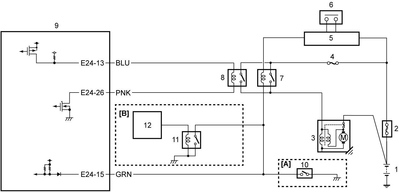
| [A]: | M/T model | 4. | “ST” fuse | 9. | ENG A-STOP control module |
| [B]: | Twin clutch system model | 5. | Keyless start control module | 10. | CPP No.1 switch |
| 1. | Battery | 6. | Engine switch | 11. | ST3 relay |
| 2. | Main fuse box | 7. | Starting motor control relay | 12. | TCM |
| 3. | Starting motor | 8. | ST2 relay |