Manual Transaxle Construction
Precautions: General safety (00)
The transaxle provides six forward speeds and one reverse speed with four synchromesh devices and three shafts: input shaft, countershaft and reverse gear shaft.
The low speed sleeve & hub is mounted on countershaft and engaged with countershaft 1st gear or 2nd gear, while the high speed sleeve & hub is mounted on input shaft and engaged with input shaft 3rd gear or 4th gear. The 5th & 6th speed sleeve & hub is mounted on input shaft and engaged with input shaft 5th gear or 6th gear. The reverse gear sleeve & hub is mounted on reverse gear shaft and engaged with reverse idler left gear or reverse idler right gear.
The triple cone synchronizing mechanism is provided to 1st and 2nd gear synchromesh devices for high performance of shifting to 2nd gear in particular. The double cone synchronizing mechanism is provided to 3rd gear synchromesh device for high performance of shifting to 3rd gear.
The gear shift control lever provides a pull-up-for-reverse mechanism. Pulling up the reverse inhibit ring under the gear shift control lever knob releases the selection restriction and allows shifting of the gear to reverse.
For servicing, it is necessary to use genuine sealant or its equivalent on mating surfaces of transaxle case. It is also important that all parts are thoroughly cleaned with cleaning fluid and air-dried before reassembling.
Further, care must be taken to adjust between case and shaft to thrust clearance of input shaft and countershaft. Synchronizer rings are inhibited from being lapped with respective gear cones using lapping compound before they are assembled.
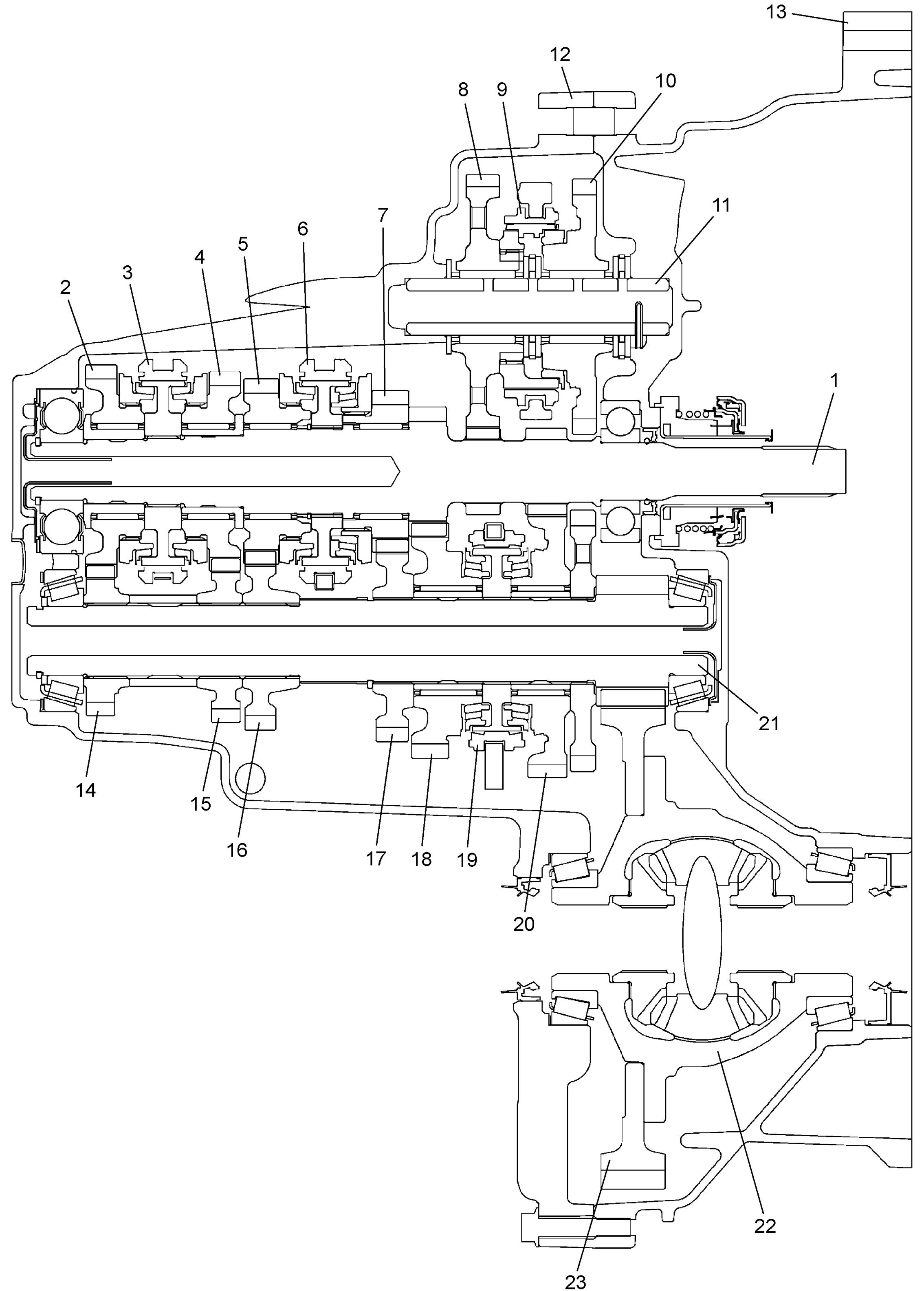
| 1. | Input shaft | 9. | Reverse gear sleeve & hub | 17. | Countershaft 3rd gear |
| 2. | Input shaft 6th gear | 10. | Reverse idler right gear | 18. | Countershaft 2nd gear |
| 3. | 5th & 6th gear sleeve & hub | 11. | Reverse gear shaft | 19. | Low speed sleeve & hub |
| 4. | Input shaft 5th gear | 12. | Transaxle left case | 20. | Countershaft 1st gear |
| 5. | Input shaft 4th gear | 13. | Transaxle right case | 21. | Countershaft |
| 6. | High speed sleeve & hub | 14. | Countershaft 6th gear | 22. | Differential case |
| 7. | Input shaft 3rd gear | 15. | Countershaft 5th gear | 23. | Final gear |
| 8. | Reverse idler left gear | 16. | Countershaft 4th gear |
Gear Shift Mechanism
The gear shifting control system consists of the following main parts. Movement of gear shift control lever is transmitted to gear shift & select shaft through gear shift and gear select control cables.
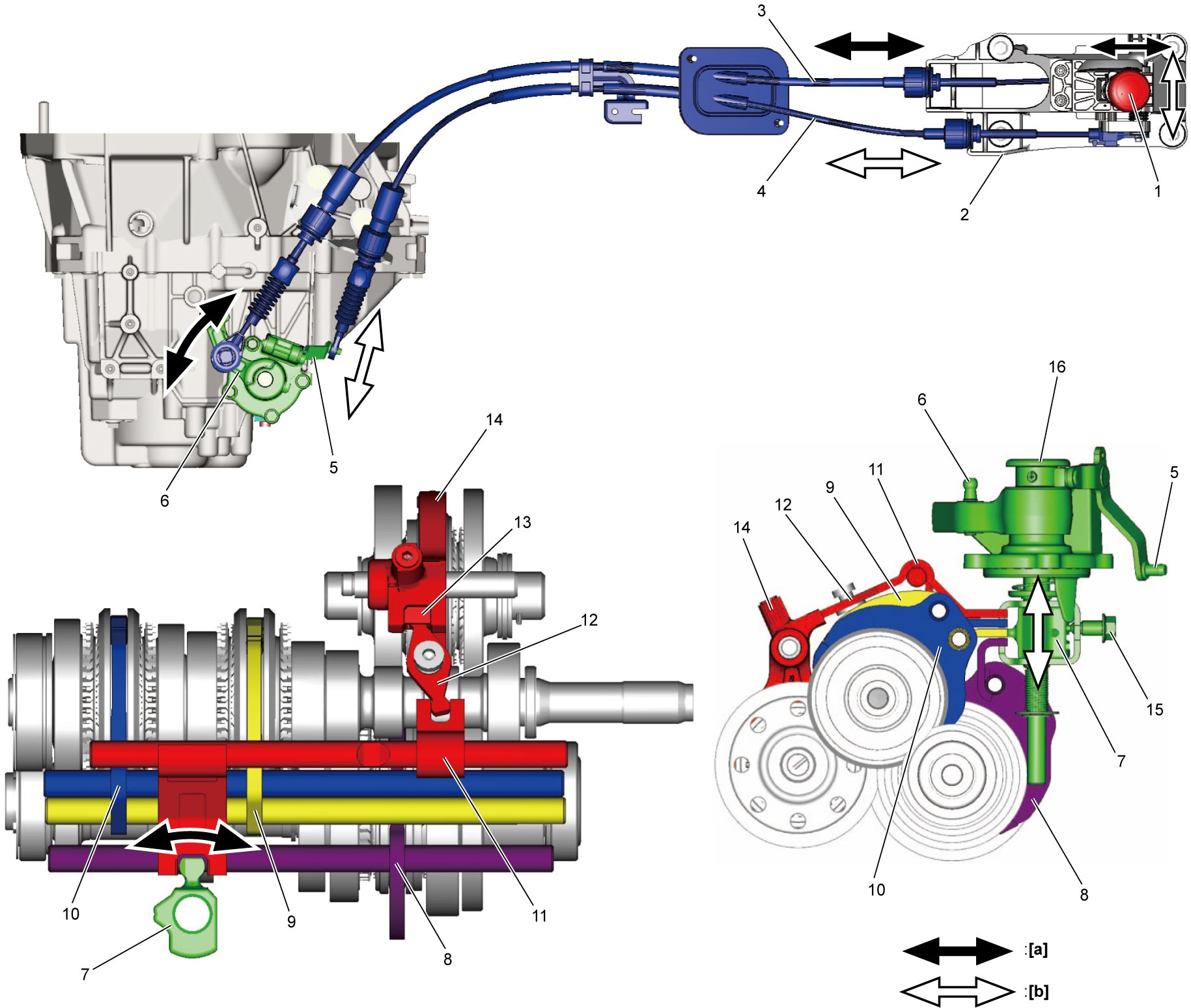
| [a]: | Direction of gear shift | 5. | Select cable lever | 11. | Reverse gear shift shaft |
| [b]: | Direction of gear select | 6. | Shift cable lever | 12. | Reverse gear shift lever |
| 1. | Gear shift control lever knob | 7. | Gear shift & select lever | 13. | Shift lever cap |
| 2. | Gear shift control lever assembly | 8. | Low speed gear shift shaft | 14. | Reverse gear shift fork |
| 3. | Gear shift control cable | 9. | High speed gear shift shaft | 15. | Gear shift interlock bolt |
| 4. | Gear select control cable | 10. | 5th & 6th gear shift shaft | 16. | Gear shift & select shaft assembly |