Select Lever Assembly Description
Precautions: Precautions for Diagnosing Trouble · Precautions for Disassembly and Reassembly · Precautions for Transmission / Transaxle · General safety (00)
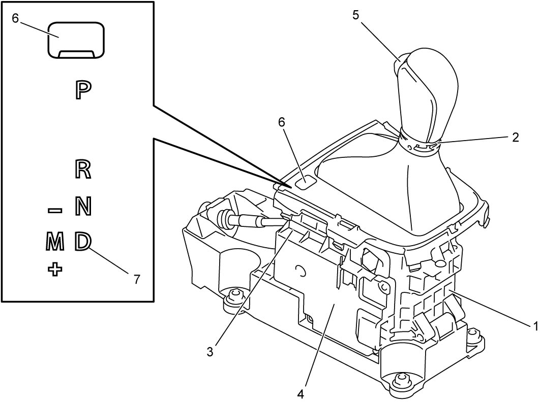
Select lever assembly (1) mainly consists of a straight type select lever (2), shift lock solenoid (inside the case) (3) and gear shift control module (4) communicating the shift information with TCM through CAN. P, R, N, D and M positions are available operating the select lever. However, shift changes from N to R, R to P and P to R require lock release operation by pressing the select lever button (detent button) (5). Each select lever position and shift lock solenoid functions as follows.
Select Lever Position and Function
| Shift range | Function |
|---|---|
| P | Gear is in neutral, parking lock wheel is locked with lock pawl, and engine is allowed to start with brake pedal depressed. |
| R | Reverse gear is engaged. |
| N | Gear is in neutral and engine is allowed to start with brake pedal depressed. |
| D | Gear shift is automatically controlled by TCM. |
| M | + (upshift) 1st → 2nd → 3rd → 4th → 5th → 6th speed |
| – (downshift) 6th → 5th → 4th → 3rd → 2nd → 1st speed |
Shift Lock Solenoid Function
X: Locked Ο: Released and select lever can be moved to R, N and D
| Select lever position | P | |||
|---|---|---|---|---|
| Ignition switch | OFF | ACC | ON | |
| Select lever button pressed | Brake applied | X | X |  |
| Brake released | X | X | X | |
In an emergency, shift lock in P can be released manually by pressing shift lock manual release button (6) without operating ignition switch and brake pedal. For LHD, removal of the button cover using small flat-bladed screwdriver or the like is required beforehand.
NOTE:
The figure shows LHD. For RHD, shift indication (7) is located at the opposite side.