Inspection of HVAC Control Unit and Its Circuit
Precautions: General safety (00)
HVAC control unit and its circuits can be checked at HVAC control unit connectors by measuring voltage.
NOTICE:
If you connect a voltmeter or an ohmmeter directly to the HVAC control unit with the HVAC control unit connector disconnected, you can damage the HVAC control unit.
Never connect a voltmeter or an ohmmeter directly to any terminal on the HVAC control unit with the HVAC control unit connector disconnected.
Voltage Check
1)Remove HVAC control unit. 
2)Connect “G154” connector and “G155” connector.
3)Check voltage at each terminal.
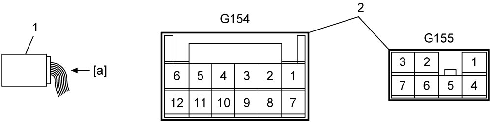

NOTE:
As each terminal voltage is affected by the battery voltage, check that battery voltage is 11 V or more with ignition “ON”.
| 1. | HVAC control unit | 2. | HVAC control unit connector (View: [a]) |
“G154” connector
| Terminal No. | Wire color | Circuit | Normal voltage | Condition |
|---|---|---|---|---|
| G154-1 | LT GRN | Ground for A/C switch | 0 – 1 V | A/C switch: OFF or A/C switch: ON and Blower speed selector: any position other than OFF |
| 10 – 14 V | A/C switch: ON and Blower speed selector: OFF |
|||
| G154-2 | PNK | Rear defogger indicator | 0 – 1 V | Rear defogger: OFF (Rear defogger indicator: OFF) |
| 10 – 14 V | Rear defogger: ON (Rear defogger indicator: ON) | |||
| G154-3 | LT GRN | Ground for illumination | Below 0.5 V | — |
| G154-5 | BLU | Air intake control actuator (Recirculation air) | 0 – 1 V | Air intake switch: “REC” position or Air intake control actuator: operating from “FRE” to “REC” |
| 10 – 14 V | Air intake switch: “FRE” position | |||
| G154-6 | GRN | Air intake control actuator (Fresh air) | 0 – 1 V | Air intake switch: “FRE” position or Air intake control actuator: operating from “REC” to “FRE” |
| 10 – 14 V | Air intake switch: “REC” position | |||
| G154-7 | WHT | A/C switch signal | 0 – 1 V | A/C switch: ON and Blower speed selector: any position other than OFF |
| 10 – 14 V | A/C switch: OFF | |||
| G154-8 | BRN | Rear defogger switch signal | Refer to Inspection of BCM and Its Circuits. | |
| G154-9 | RED | Illumination switch | 0 – 1 V | Lighting switch: OFF position |
| 10 – 14 V | Lighting switch: ON position | |||
| G154-11 | YEL | Power supply | 0 – 1 V | Ignition: “OFF” |
| 10 – 14 V | Ignition: “ON” | |||
| G154-12 | GRY | Ground for HVAC control unit | Below 0.5 V | — |
“G155” connector
| Terminal No. | Wire color | Circuit | Normal voltage | Condition |
|---|---|---|---|---|
| G155-1 | BLK | Ground for blower speed selector | Below 0.5 V | — |
| G155-2 | RED | Blower speed selector (1st) | 10 – 14 V | Blower speed selector: OFF position |
| 0 – 1 V | Blower speed selector: other than above condition | |||
| G155-3 | GRY | Blower speed selector (2nd) | 10 – 14 V | Blower speed selector: OFF position |
| 0 – 1 V | Blower speed selector: at each of 2nd to 4th positions | |||
| G155-5 | LT GRN | Ground for A/C switch | 0 – 1 V | A/C switch: OFF or A/C switch: ON and Blower speed selector: any position other than OFF |
| 10 – 14 V | A/C switch: ON and Blower speed selector: OFF position |
|||
| G155-6 | WHT | Blower speed selector (4th) | 10 – 14 V | Blower speed selector: OFF position |
| 0 – 1 V | Blower speed selector: 4th position | |||
| G155-7 | YEL | Blower speed selector (3rd) | 10 – 14 V | Blower speed selector: OFF position |
| 0 – 1 V | Blower speed selector: 3rd and 4th positions |