DTC Check
Precautions: Precautions for Diagnosing Trouble · General safety (00)
1)Set ignition “OFF”.
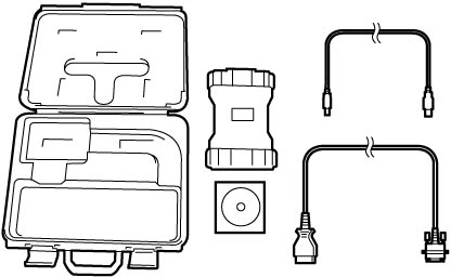
2)Connect SUZUKI scan tool to DLC (1).
3)Light sunload sensor with an incandescent light of approximately 100 W placed directly above it at distance of about 100 mm (3.94 in.).
NOTE:
DTC B1504 is detected even though there is not any malfunction if sunload sensor is not lit by an incandescent light. Light the sunload sensor with a light.
4)Set ignition “ON”.
5)Read DTC according to instructions displayed on SUZUKI scan tool and print it or write it down. Refer to Operator's Manual of SUZUKI scan tool for further details.
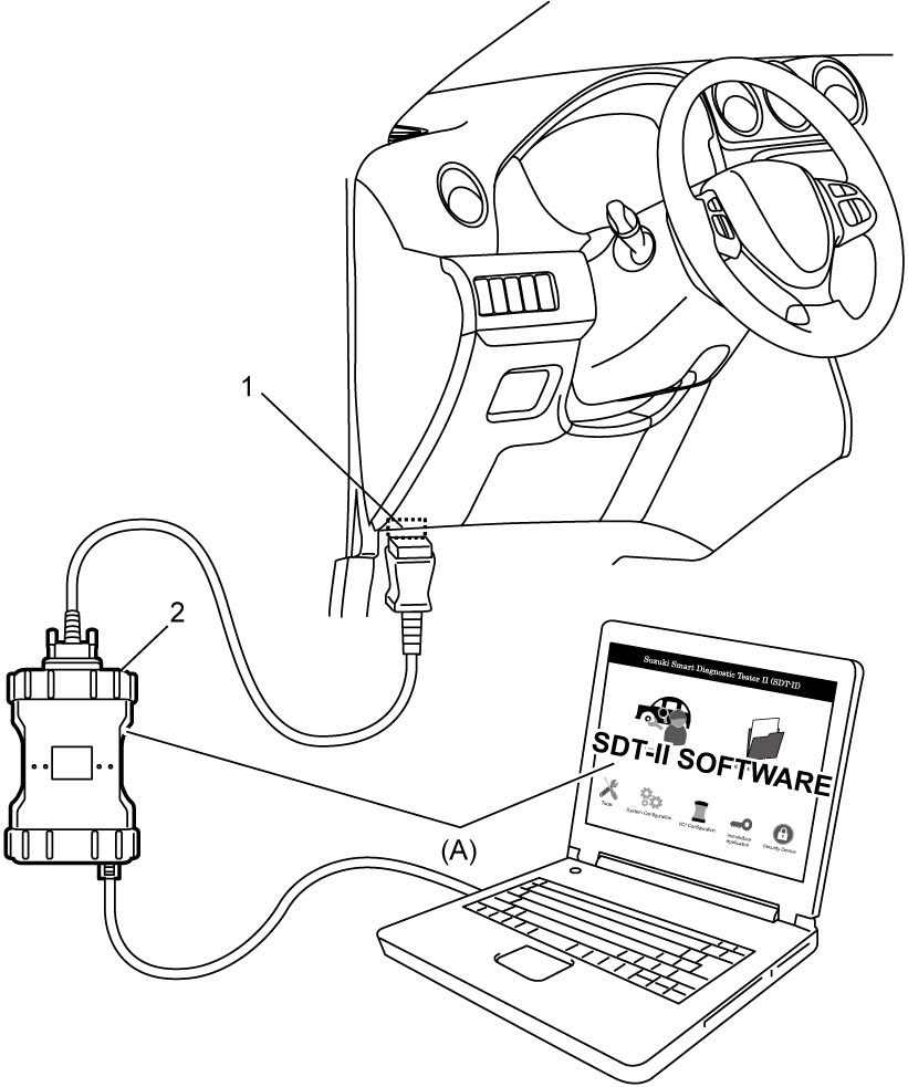

NOTE:
If communication between SUZUKI scan tool and HVAC control module is not possible, perform the following checks:
•Check communication condition between PC and VCI (2) using SUZUKI scan tool function.
•Check DLC power circuit and ground circuit.
•Check DLC cable. If necessary, check DLC cable by substituting a known-good DLC cable.
•Check CAN communication system. (“Control Module Communication Bus Off” is detected in any control module.)

•Check DLC power circuit and ground circuit.
•Check DLC cable. If necessary, check DLC cable by substituting a known-good DLC cable.
•Check CAN communication system. (“Control Module Communication Bus Off” is detected in any control module.)
—M16A model:
—K14C model:
—D16AA model:
•Check HVAC control module power circuit and ground circuit. —K14C model:
—D16AA model:
6)After completing the check, set ignition “OFF” and disconnect SUZUKI scan tool from DLC.