Immobilizer Control System Component Location
Precautions: Precautions for Diagnosing Trouble · General safety (00)
NOTE:
The figure shows LHD. For RHD, parts with (*) are installed at the opposite side.
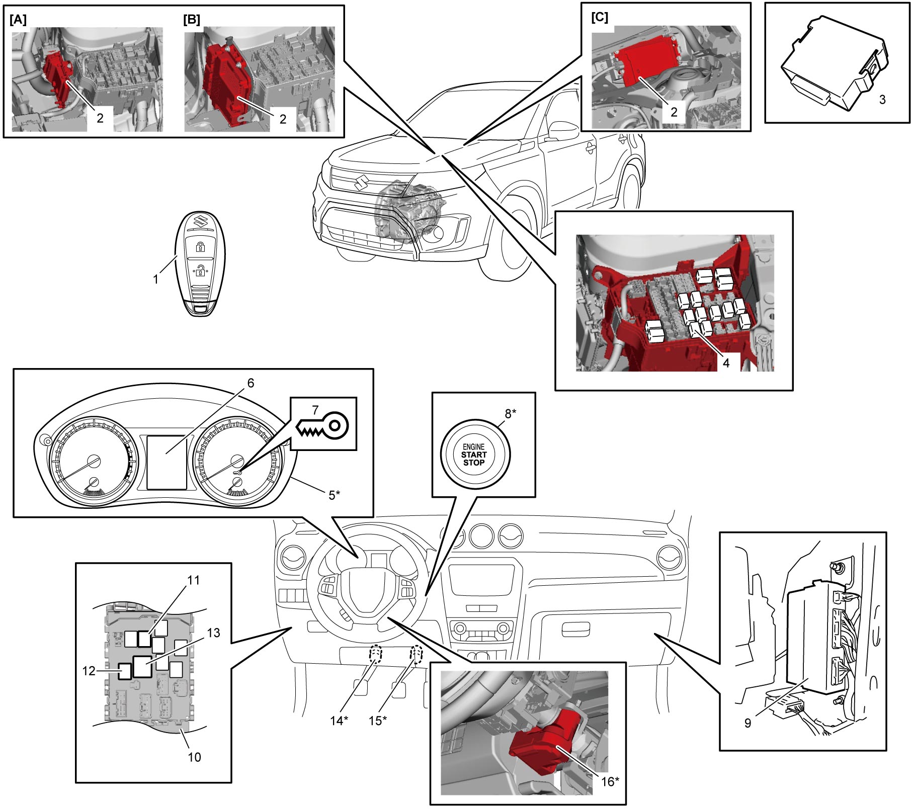
| [A]: | M16A model | 5. | Combination meter | 12. | IG1 relay |
| [B]: | K14C model | 6. | Information display | 13. | IG2 relay |
| [C]: | D16AA model | 7. | Immobilizer indicator light | 14. | CPP No.1 switch (M/T model) |
| 1. | Remote controller | 8. | Engine switch | 15. | Brake light switch |
| 2. | ECM | 9. | Keyless start control module | 16. | Steering lock unit |
| 3. | ID controller (if equipped) | 10. | J/B (back side) | ||
| 4. | Starting motor control relay | 11. | ACC relay |