CAN Communication System Circuit Diagram
Precautions: Precautions for Diagnosing Trouble · General safety (00)
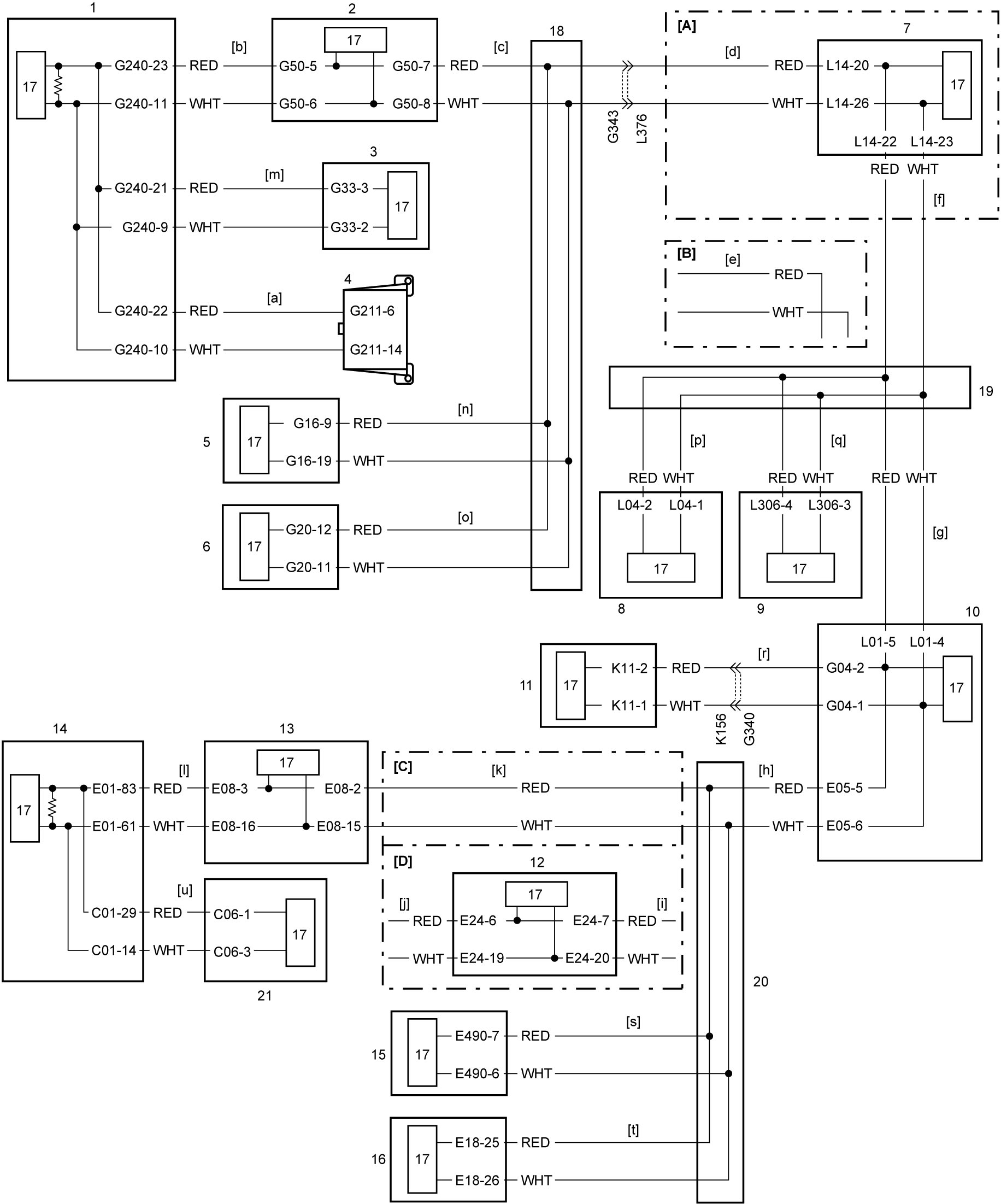
| [A]: | 4WD model | 4. | DLC | 13. | ESP® control module |
| [B]: | 2WD model | 5. | Keyless start control module | 14. | ECM |
| [C]: | Non-ENG A-STOP model | 6. | HVAC control module | 15. | RBS control module (RBS model) |
| [D]: | ENG A-STOP model | 7. | 4WD control module | 16. | Headlight auto leveling control module |
| [a] to [u]: | CAN communication line (linked with diagnosis flows [a] to [u] of “Diagnosis Flow Selection Table”) | 8. | SDM | 17. | CAN driver |
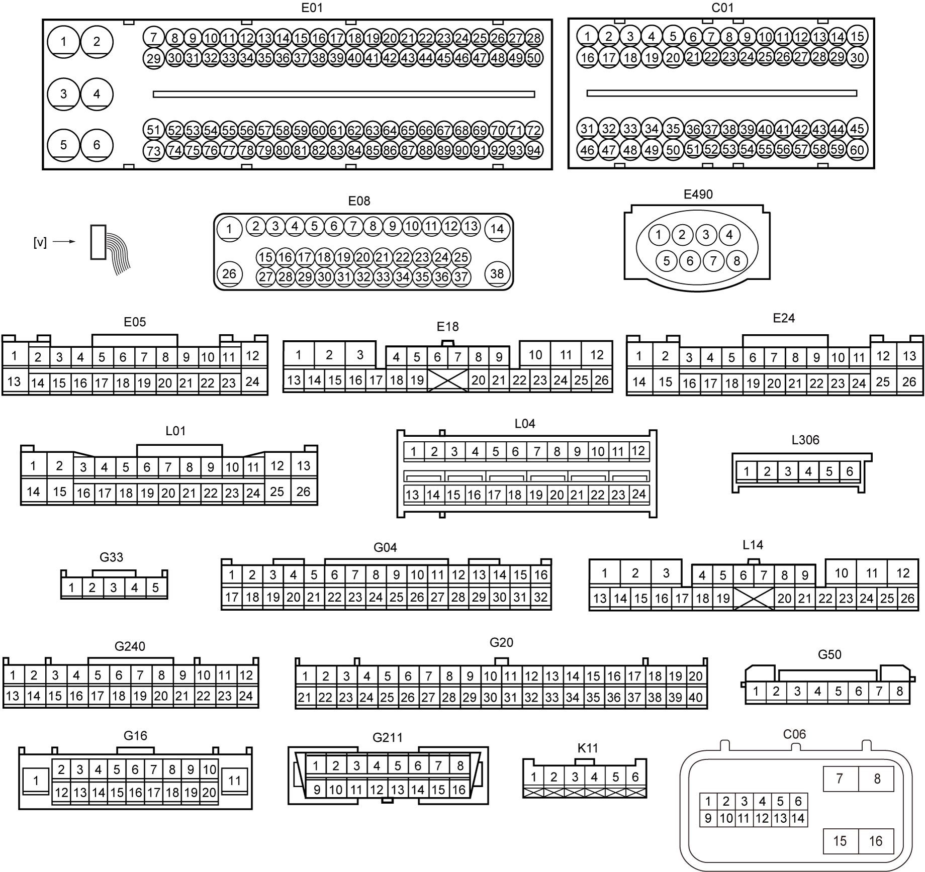
| [v]: | Connector view | 9. | TPMS control module (TPMS model) | 18. | J/C (G310) |
| 1. | Combination meter | 10. | BCM | 19. | J/C (L346) |
| 2. | P/S control module | 11. | Rain / light sensor | 20. | J/C (E346) |
| 3. | Steering angle sensor | 12. | ENG A-STOP control module | 21. | TCM (A/T model) |