| OK |  |
| Go to step 3 |
DTC P0724 Brake Switch "B" Circuit High |
| DTC No. | DTC Detection Condition | Trouble Area |
| P0724 | The stop light switch remains ON even when the vehicle is driven in a STOP (less than 3 km/h (2 mph)) and GO (30 km/h (19 mph) or more) fashion 5 times. (2-trip detection logic). |
|
| Related DTCs | P0724: Stop light switch/Range check/Rationality |
| Required sensors/Components | Stop light switch, Vehicle speed sensor |
| Frequency of operation | Continuous |
| Duration | GO and STOP 5 times |
| MIL operation | 2 driving cycles |
| Sequence of operation | None |
| The monitor will run whenever this DTC is not present. | None |
| GO: (Vehicle speed is 18.63 mph (30 km/h) or more) | Once |
| STOP: (Vehicle speed is less than 1.86 mph (3 km/h)) | Once |
| Starter | OFF |
| Battery voltage | 8 V or more |
| Ignition switch | ON |
| Brake switch | Remain ON during GO and STOP 5 times |
| 1.READ VALUE OF DATA LIST (STP SIGNAL) |
Turn the ignition switch off.
Connect the intelligent tester together with the CAN VIM (controller area network vehicle interface module) to the DLC3.
Turn the ignition switch to the ON position.
Turn on the tester.
Select the item "DIAGNOSIS / OBD/MOBD / ECT / DATA LIST".
According to the display on the tester, read the "DATA LIST".
| Item | Measurement Item/Range (display) | Normal Condition |
| STOP LIGHT SW | Stop light switch Status/ON or OFF |
|
|
| ||||
| NG | |
 |
| 2.INSPECT STOP LIGHT SWITCH ASSEMBLY |
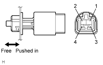 |
Remove the stop light switch assembly.
Measure the resistance according to the value(s) in the table below.
| Switch position | Tester Connection | Specified Condition |
| Switch pin free | 1 - 2 | Below 1 Ω |
| Switch pin pushed in | ↑ | 10 kΩ or higher |
| Switch pin free | 3 - 4 | 10 kΩ or higher |
| Switch pin pushed in | ↑ | Below 1 Ω |
|
| ||||
| OK | |
|
| 3.CHECK HARNESS AND CONNECTOR (STOP LIGHT SWITCH ASSEMBLY - ECM) |
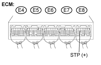 |
Install the stop light switch assembly.
Disconnect the ECM connector.
Measure the voltage according to the value(s) in the table below when the brake pedal is depressed and released.
| Condition | Tester Connection | Specified Condition |
| Brake pedal is depressed | E8-15 (STP) - Body ground | 10 to 14 V |
| Brake pedal is released | ↑ | Below 1 V |
|
| ||||
| OK | ||
 | ||
| ||
