Home › COMMUNICATION SYSTEM › MULTIPLEX COMMUNICATION › MULTIPLEX COMMUNICATION SYSTEM

DTC    B1214    Short to B+ in Door System Communication Bus Malfunction

DTC    B1215    Short to GND in Door System Communication Bus Malfunction

for Preparation Click here


DESCRIPTION

  1. B1214 and B1215 are output when +B and the body ground is short-circuited on the communication bus. Detecting this condition disables all the BEAN communication and outputs some DTCs.

DTC No.
DTC Detection Condition
Trouble Area
B1214
Door system communication circuit and +B battery system short
  1. Theft warning ECU assembly (Theft deterrent ECU)
  2. Multiplex network door ECU back (Back door ECU)
  3. Wire harness
  4. Instrument panel junction block assembly (Body ECU)
B1215
Door system communication circuit and body ground short
  1. Theft warning ECU assembly (Theft deterrent ECU)
  2. Multiplex network door ECU back (Back door ECU)
  3. Wire harness
  4. Instrument panel junction block assembly (Body ECU)

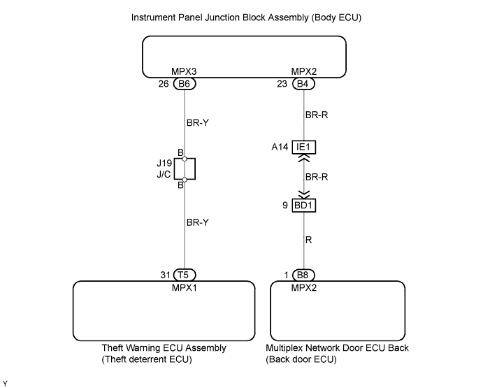
WIRING DIAGRAM


B065155E02


INSPECTION PROCEDURE

1.CHECK DIAGNOSTIC TROUBLE CODE (A ECU)


  1. Check whether the output of the DTC stops when the A ECU connector is disconnected.
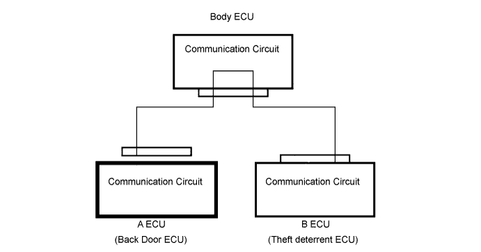

    B063900E01

    NOTICE:
    Disconnect the connectors in the operational sequence, and start the next step after the connector in connected.

    HINT:
    In this case, the A ECU in the represents the back door ECU.

    OK:
    When the output of the DTC stops, the disconnected A ECU is abnormal.


OK
REPLACE A ECU
NG


2.CHECK DIAGNOSTIC TROUBLE CODE (B ECU)


  1. Check whether the output of the DTC stops when the B ECU connector is disconnected.
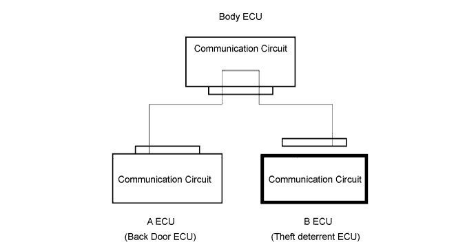

    B065156E01

    OK:
    Neither DTC B1214 nor DTC B1215 is output.

    NOTICE:
    Disconnect the connectors in the operational sequence, and start the next step after the connector in connected.

    HINT:
    In this case, the B ECU in the represents the theft deterrent ECU.

    OK:
    When the output of the DTC stops, the disconnected B ECU is abnormal.


OK
REPLACE B ECU
NG


3.CHECK WIRE HARNESS BETWEEN BODY ECU AND A ECU OR B ECU
  1. Disconnect the A ECU, B ECU and body ECU connectors.


  1. Check the wire harness (MPX line) between the A ECU, B ECU and body ECU.
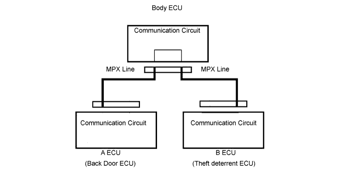

    B063902E01

    1. Turn the ignition switch ON.

    2. Check the voltage between the wire harness (MPX line) and body ground.

      Standard voltage:

      MPX line - Body ground
      Specified Condition
      Body ECU or A ECU (Back door ECU) - Body ground
      Below 1 V
      Body ECU or B ECU (Theft deterrent ECU) - Body ground
      Below 1 V

      If the output voltage is not Below 1V, the wire harness (MPX line) may be short-circuited with +B.

    3. Check the resistance of the wire harness (MPX lines) and body ground.

      Standard resistance:

      MPX line - Body ground
      Specified Condition
      Body ECU or A ECU (Back door ECU) - Body ground
      10 kΩ or higher
      Body ECU or B ECU (Theft deterrent ECU) - Body ground
      10 kΩ or higher

      If there is Below 1 Ω, the wire harness (MPX line) and body ground may be short-circuited with the body ground.


NG
REPAIR OR REPLACE WIRE HARNESS BETWEEN BODY ECU AND A ECU OR B ECU
OK

REPLACE INSTRUMENT PANEL JUNCTION BLOCK ASSEMBLY