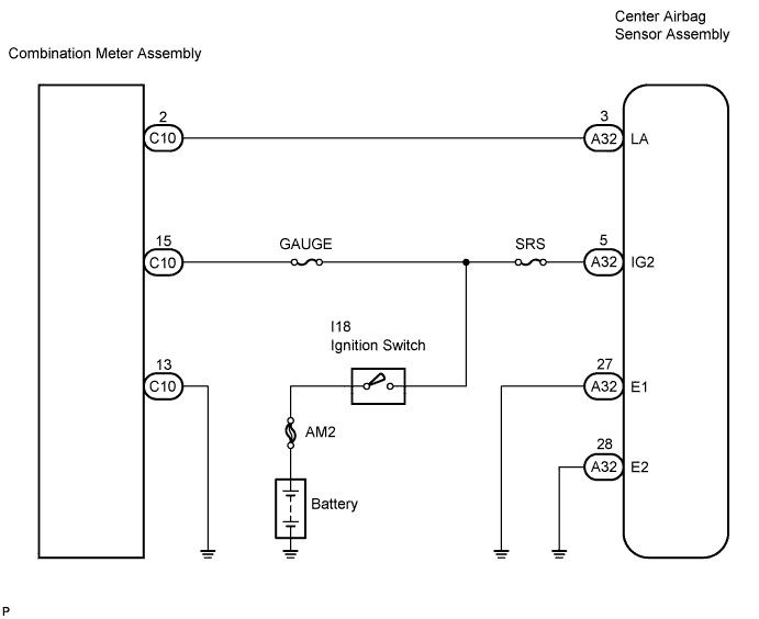
AIRBAG SYSTEM > SRS Warning Light Remains ON |
| 1.CHECK SRS WARNING LIGHT OPERATION |
Check the SRS warning light operation approximately 6 seconds after the ignition switch is turned to the ON position.
| SRS Warning Light Illumination | Proceed to |
| Remains on after it goes off | A |
| Remains on | B |
|
| ||||
| A | |
 |
| 2.CHECK BATTERY |
Measure the voltage of the battery.
|
| ||||
| OK | |
|
| 3.CHECK CONNECTOR |
Turn the ignition switch to the LOCK position.
Disconnect the negative (-) terminal cable from the battery, and wait for at least 90 seconds.
Check that the connector is properly connected to the center airbag sensor assembly.
|
| ||||
| OK | |
|
| 4.CHECK WIRE HARNESS (SOURCE VOLTAGE OF CENTER AIRBAG SENSOR ASSEMBLY) |
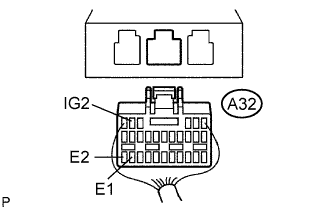 |
Disconnect the connectors from the center airbag sensor assembly.
Connect the negative (-) terminal cable to the battery, and wait for at least 2 seconds.
Turn the ignition switch to the ON position.
Operate all components of the electrical system (defogger, wipers, headlight, heater blower, etc.).
Measure the voltage according to the value(s) in the table below.
| Tester connection | Condition | Specified condition |
| A32-5 (IG2) - Body ground | Ignition switch ON | 10 to 14 V |
Turn the ignition switch to the LOCK position.
Measure the resistance according to the value(s) in the table below.
| Tester connection | Condition | Specified condition |
| A32-27 (E1) - Body ground | Always | Below 1 Ω |
| A32-28 (E2) - Body ground | Always | Below 1 Ω |
|
| ||||
| OK | |
|
| 5.CHECK SRS WARNING LIGHT |
Connect the negative (-) terminal cable to the battery, and wait for at least 2 seconds.
Turn the ignition switch to the ON position.
Check the SRS warning light condition.
|
| ||||
| OK | ||
 | ||
| ||
| 6.CHECK BATTERY |
Measure the voltage of the battery.
|
| ||||
| OK | |
|
| 7.CHECK CONNECTORS |
Turn the ignition switch to the LOCK position.
Disconnect the negative (-) terminal cable from the battery, and wait for at least 90 seconds.
Check that the connectors are properly connected to the center airbag sensor assembly and combination meter assembly.
|
| ||||
| OK | |
|
| 8.CHECK WIRE HARNESS (SOURCE VOLTAGE OF CENTER AIRBAG SENSOR ASSEMBLY) |
|
Disconnect the connectors from the center airbag sensor assembly.
Connect the negative (-) terminal cable to the battery, and wait for at least 2 seconds.
Turn the ignition switch to the ON position.
Operate all components of the electrical system (defogger, wipers, headlight, heater blower, etc.).
Measure the voltage according to the value(s) in the table below.
| Tester connection | Condition | Specified condition |
| A32-5 (IG2) - Body ground | Ignition switch ON | 10 to 14 V |
Turn the ignition switch to the LOCK position.
Measure the resistance according to the value(s) in the table below.
| Tester connection | Condition | Specified condition |
| A32-27 (E1) - Body ground | Always | Below 1 Ω |
| A32-28 (E2) - Body ground | Always | Below 1 Ω |
|
| ||||
| OK | |
|
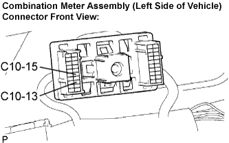
| 9.CHECK WIRE HARNESS (SOURCE VOLTAGE OF COMBINATION METER) |
 |
Disconnect the negative (-) terminal cable from the battery, and wait for at least 90 seconds.
Remove the combination meter assembly (Click here).
Connect the negative (-) terminal cable to the battery, and wait for at least 2 seconds.
Turn the ignition switch to the ON position.
Measure the voltage according to the value(s) in the table below.
| Tester connection | Condition | Specified condition |
| C10-15 - Body ground | Ignition switch ON | 10 to 14 V |
Turn the ignition switch to the LOCK position.
Measure the resistance according to the value(s) in the table below.
| Tester connection | Condition | Specified condition |
| C10-13 - Body ground | Always | Below 1 Ω |
|
| ||||
| OK | |
|
| 10.CHECK WIRE HARNESS (OPEN) |
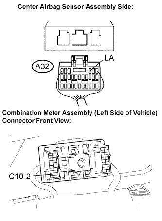 |
Measure the resistance according to the value(s) in the table below.
| Tester connection | Condition | Specified condition |
| A32-3 (LA) - C10-2 | Always | Below 1 Ω |
|
| ||||
| OK | |
|
| 11.CHECK WIRE HARNESS (SHORT TO GROUND) |
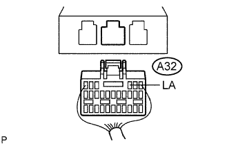 |
Measure the resistance according to the value(s) in the table below.
| Tester connection | Condition | Specified condition |
| A32-3 (LA) - Body ground | Always | 1 MΩ or higher |
|
| ||||
| OK | |
|
| 12.CHECK WIRE HARNESS (SHORT TO B+) |
|
Turn the ignition switch to the ON position.
Measure the resistance according to the value(s) in the table below.
| Tester connection | Condition | Specified condition |
| A32-3 (LA) - Body ground | Always | 1 MΩ or higher |
|
| ||||
| OK | |
|
| 13.CHECK SRS WARNING LIGHT |
Turn the ignition switch to the LOCK position.
Disconnect the negative (-) terminal cable from the battery, and wait for at least 90 seconds.
Install the combination meter assembly (Click here).
Connect the negative (-) terminal cable to the battery, and wait for at least 2 seconds.
Turn the ignition switch to the ON position.
Check the SRS warning light condition.
|
| ||||
| OK | ||
| ||
| ||

