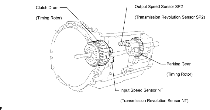
DTC P0722 Output Speed Sensor Circuit No Signal |
| DTC No. | DTC Detection Condition | Trouble Area |
| P0722 | All conditions below are detected 500 times or more continuously (1-trip detection logic) (a) No signal from speed sensor (SP2) is input to ECM while 4 pulses of No. 1 vehicle speed sensor signal are sent (b) Vehicle speed is 9 km/h (6 mph) or more for at least 4 sec. (c) Park/neutral position switch is OFF. |
|
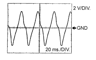
| Terminal | SP2+ - SP2- |
| Tool setting | 2 V/DIV., 20 ms./DIV |
| Vehicle condition | Vehicle speed 20 km/h (12 mph) |
| Related DTCs | P0722 : Speed sensor SP2/Verify pulse input |
| Required Sensors/Components | Speed sensor SP2 |
| Frequency of operation | Continuous |
| Duration | 500 output shaft revolution |
| MIL operation | Immediate |
| Sequence of operation | None |
| The monitor will run whenever this DTC is not present. | P0500 (VSS) P0748 (Trans solenoid (range)) |
| Vehicle speed sensor pulse input | 4 |
| Vehicle speed range (4 sec. or more) | 9 km/h (5.59 mph) or more |
| NSW switch | OFF |
| Battery voltage | 8 V or more |
| Ignition switch | ON |
| Starter | OFF |
| Output speed sensor pulse input | No input |
| DATA LIST |
Warm up the engine.
Turn the ignition switch off.
Connect the intelligent tester together with the CAN VIM (controller area network vehicle interface module) to the DLC3.
Turn the ignition switch to the ON position.
Turn on the tester.
Select the item "DIAGNOSIS / OBD/MOBD / ECT / DATA LIST".
According to the display on the tester, read the "DATA LIST".
| Item | Measurement Item/Range (display) | Normal Condition |
| SPD (SP2) | Output shaft Speed/min.: 0 km/h (0 mph) max.: 255 km/h (158 mph) | Vehicle stopped: 0 km/h (0 mph)
|
| 1.INSPECT SPEED SENSOR INSTALLATION |
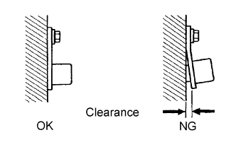 |
Check the speed sensor (SP2) installation.
|
| ||||
| OK | |
 |
| 2.INSPECT SPEED SENSOR (SP2) |
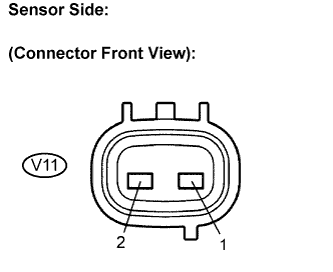 |
Disconnect the speed sensor connector from the transmission.
Measure the resistance according to the value(s) in the table below.
| Tester Connection | Specified Condition 20°C (68°F) |
| 1 - 2 | 560 to 680 Ω |
|
| ||||
| OK | |
|
| 3.CHECK WIRE HARNESS AND CONNECTOR (SPEED SENSOR SP2 - ECM) |
 |
Connect the speed sensor connector.
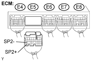
Disconnect the ECM connector.
Measure the resistance according to the value(s) in the table below.
| Tester Connection | Specified Condition 20°C (68°F) |
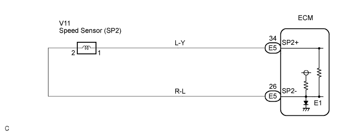
| E5-34 (SP2+) - E5-26 (SP2-) | 560 to 680 Ω |
Measure the resistance according to the value(s) in the table below.
| Tester Connection | Specified Condition |
| E5-34 (SP2+) - Body ground | 10 kΩ or higher |
| E5-26 (SP2-) - Body ground | ↑ |
|
| ||||
| OK | ||
 | ||
| ||
