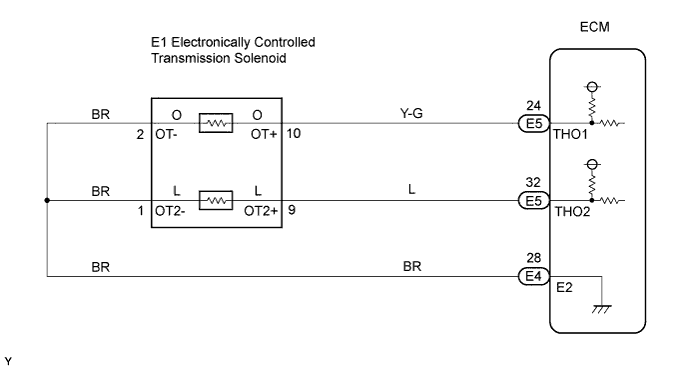
DTC P2740 Transmission Fluid Temperature Sensor "B" Circuit |
DTC P2742 Transmission Fluid Temperature Sensor "B" Circuit Low Input |
DTC P2743 Transmission Fluid Temperature Sensor "B" Circuit High Input |
| No. 2 ATF Temperature Sensor State | Detection Condition | Symptom | Recovery Condition |
| Sensor is normal | ATF temperature more than 150°C (275°F) | A/T OIL TEMP warning light remains ON | ATF temperature less than 135°C (275°F)*2 |
| ATF temperature more than 130°C (266°F) | Shift point too high | ATF temperature less than 110°C (230°F) | |
| When the conditions (a) and (b) are satisfied. (a) ATF temperature more than 130°C (266°F) (b) Engine coolant temperature more than 95°C (203°F) | Lock-up at 3rd gear*1 | ATF temperature less than 110°C (230°F)*2 and engine coolant temperature more than 95°C (203°F) | |
| Sensor is short-circuited | Any conditions |
| Symptoms still occur |
| Engine coolant temperature more than 95°C (203°F) | Lock-up at 3rd gear*1 | Symptoms still occur |
| DTC No. | DTC Detection Condition | Trouble Area |
| P2740 | (a) and (b) are detected momentarily within 0.5 seconds when neither P2742 or P2743 are detected. (1-trip detection logic) (a) No. 2 ATF temperature sensor resistance is less than 25 Ω (0.046 V). (b) No. 2 ATF temperature sensor resistance is more than 156 kΩ (4.915 V).
|
|
| P2742 | No. 2 ATF temperature sensor resistance is less than 25 Ω (0.046 V) for 0.5 seconds or more. (1-trip detection logic) |
|
| P2743 | No. 2 ATF temperature sensor resistance is more than 156 kΩ (4.915 V) when 15 minutes or more have passed after the engine start. DTC is detected for 0.5 seconds or more. (1-trip detection logic) |
|
| Related DTCs | P2740: ATF temperature sensor/Range check (Fluttering) P2742: ATF temperature sensor/Range check (Low resistance) P2743: ATF temperature sensor/Range check (High resistance) |
| Required sensors/Components | ATF temperature sensor |
| Frequency of operation | Continuous |
| Duration | 0.5 seconds |
| MIL operation | Immediate |
| Sequence of operation | None |
| The monitor will run whenever the following DTCs are not present | None |
| The typical enabling condition is not available. | - |
| Time after engine start | 15 minutes or more |
| TFT (Transmission fluid temperature) sensor voltage | Less than 0.046 V or More than 4.915 V |
| TFT (Transmission fluid temperature) sensor voltage | Less than 0.046 V |
| TFT (Transmission fluid temperature) sensor voltage | More than 4.915 V |
| TFT (Transmission fluid temperature) sensor | Atmospheric temperature up to approximately 130°C (266°F) |
| DATA LIST |
| Item | Measurement Item/Range (Display) | Normal Condition | Diagnostic Note |
| AT FLUID TEMP 2 | No. 2 ATF temperature sensor value/Min.: -40°C (-40°F) Max.: 215°C (419°F) |
| If value is -40°C (-40°F) or 215°C (419°F), No. 2 ATF temperature sensor circuit is opened or short circuited |
| Temperature Displayed | Malfunction |
| -40°C (-40°F) | Open circuit |
| 150°C (302°F) or more | Short circuit |
| 1.INSPECT TRANSMISSION WIRE (NO. 2 ATF TEMPERATURE SENSOR) |
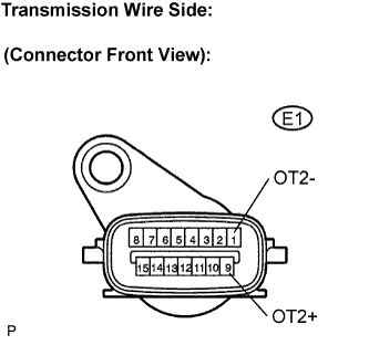 |
Disconnect the transmission wire connector.
Measure the resistance.
| Tester Connection | Specified Condition |
| 1 (OT2-) - 9 (OT2+) | 25 Ω to 156 kΩ |
| 1 (OT2-) - Body ground | 10 kΩ or higher |
| 9 (OT2+) - Body ground | 10 kΩ or higher |
| ATF temperature | Specified Condition |
| 20°C (68°F) | 3 to 4 kΩ |
| 110°C (230°F) | 0.22 to 0.28 kΩ |
|
| ||||
| OK | |
 |
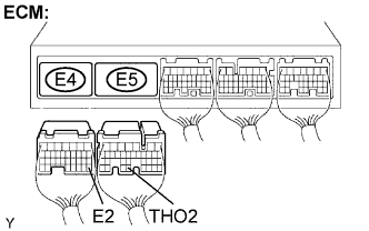
| 2.CHECK WIRE HARNESS AND CONNECTOR (TRANSMISSION WIRE - ECM) |
 |
Connect the transmission wire connector to the transmission.
Disconnect the ECM connector.
Measure the resistance according to the value(s) in the table below.
| Tester Connection | Specified Condition |
| E5-32 (THO2) - E4-28 (E2) | 79 Ω to 156 kΩ |
Measure the resistance according to the value(s) in the table below.
| Tester Connection | Specified Condition |
| E5-32 (THO2) - Body ground | 10 kΩ or higher |
| E4-28 (E2) - Body ground | ↑ |
|
| ||||
| OK | ||
 | ||
| ||
