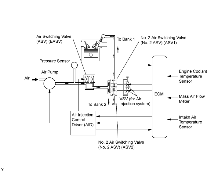
DTC P0412 Secondary Air Injection System Switching Valve "A" Circuit |
| DTC No. | DTC Detection Condition | Trouble Area |
| P0412 | Both of the following conditions are met when engine is idling just after cold start (1 trip detection logic):
|
|
| P0412 | Both of the following conditions are met when engine is idling just after cold start (1 trip detection logic):
|
|
| Related DTCs | P0412: Air switching valve circuit malfunction (Secondary air injection system) |
| Required sensors/components | Air injection control driver, Air switching valve |
| Frequency of operation | Continuous |
| Duration | 3 seconds |
| MIL operation | Immediate |
| Sequence operation | None |
| The monitor will run whenever this DTC is not present | None |
| Air pump | Operating |
| Air switching valve | Operating |
| Battery voltage | 8 V or more |
| Ignition switch | ON |
| Starter | OFF |
| Air pump | Not operating |
| Air switching valve | Not operating |
| Battery voltage | 8 V or more |
| Ignition switch | ON |
| Starter | OFF |
| Diagnostic signal duty ratio from air injection driver | 31 to 48 % |
| Diagnostic signal duty ratio from air injection control driver | 70 to 90 % when secondary air injection system operating and 0 % when secondary air injection system not operating |
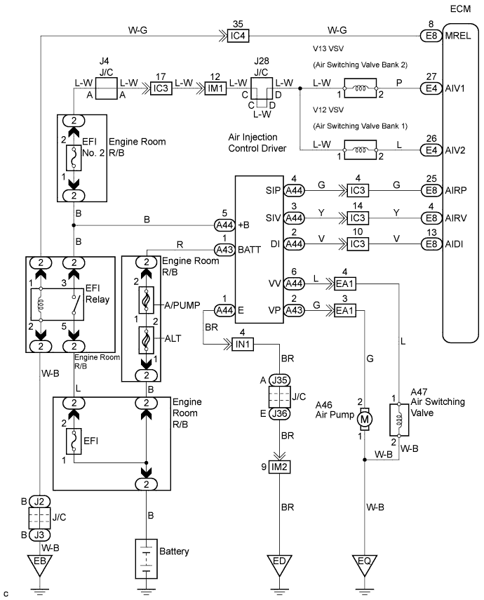
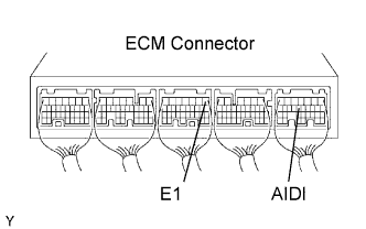 |
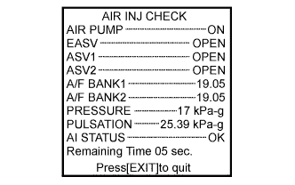 |
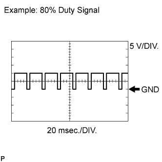 |
| Items | Contents |
| Terminals | CH1: AIDI - E1 |
| Equipment Settings | 5 V/DIV., 20 to 40 ms/DIV. |
| Conditions | Idling |
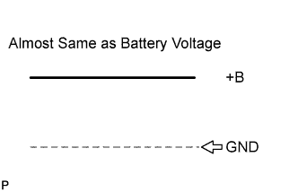
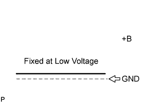
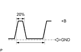
| AID Diagnostic Signal Waveform | ECM Command | DTC (ECM Output) | Suspected Trouble Area |
| 100 % Duty Ratio See waveform 1 | Any Air Injection (AIR) System operation | P1613 |
|
| 0 % Duty Ratio See waveform 2 | AIR System: ON (Air pump ON, ASV ON) | P1613 |
|
| AIR System: OFF (Air pump OFF, ASV OFF) | - |
| |
| 20 % Duty Ratio See waveform 3 | Air Pump: ON | P0418 |
|
| Air Pump: OFF | P0418 |
| |
| 40 % Duty Ratio See waveform 4 | ASV: ON | P0412 |
|
| ASV: OFF | P0412 |
| |
| 80 % Duty Ratio See waveform 5 | AIR System: OFF (Air pump OFF, ASV OFF) | P1613 |
|
| AIR System: ON (Air pump ON, ASV ON) | - |
| |
| Excluding Above (excluding 0, 20, 40, 80, 100 % duty) | - | P1613 |
|
| Waveform 1 |
 |
| Waveform 2 |
 |
| Waveform 3 |
 |
| Waveform 4 |
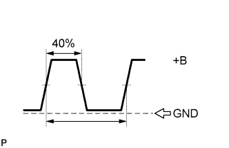 |
| Waveform 5 |
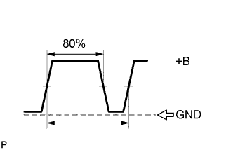 |
| 1.INSPECT AIR SWITCHING VALVE |
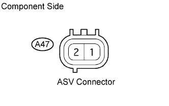 |
Remove the intake manifold .
Disconnect the A47 Air Switching Valve (ASV) connector.
Measure the resistance of the ASV.
| Tester Connection | Specified Condition |
| 1 - 2 | 4.5 to 5.5 Ω |
Reconnect the ASV connector.
|
| ||||
| OK | |
 |
| 2.CHECK HARNESS AND CONNECTOR (AIR SWITCHING VALVE - BODY GROUND) |
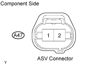 |
Remove the intake manifold .
Disconnect the A47 ASV connector.
Check the resistance between the wire harness side connector and body ground.
| Tester Connection | Specified Condition |
| A47-2 - Body ground | Below 1 Ω |
Reconnect the ASV connector.
|
| ||||
| OK | |
|
| 3.CHECK HARNESS AND CONNECTOR (AIR SWITCHING VALVE - AIR INJECTION CONTROL DRIVER) |
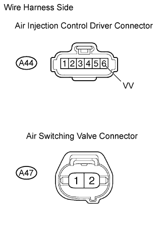 |
Remove the intake manifold .
Disconnect the A44 air injection driver connector.
Disconnect the A47 air switching valve connector.
Measure the resistance between the wire harness side connectors.
| Tester Connection | Specified Condition |
| VV (A44-6) - A47-1 | Below 1 Ω |
| VV (A44-6) or A47-1 - Body ground | 10 kΩ higher |
Reconnect the air injection driver connector.
Reconnect the ASV connector.
|
| ||||
| OK | ||
 | ||
| ||
