 |
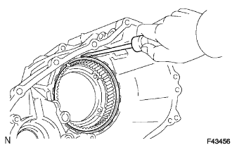
Using a screwdriver, install the snap ring.
TRANSFER ASSEMBLY > REASSEMBLY |
| 1. INSTALL TRANSFER LOW PLANETARY RING GEAR |
Install the low planetary ring gear to the front case.
|
Using a screwdriver, install the snap ring.
| 2. INSTALL WITH HEAD PIN |
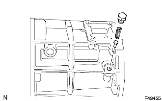 |
Install w/ head pin.
| 3. INSTALL COMPRESSION SPRING |
| 4. INSTALL TRANSFER CASE PLUG |
| 5. INSTALL TRANSFER OUTPUT SHAFT PLATE WASHER |
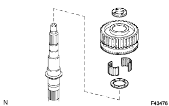 |
Install the transfer output shaft plate washer.
| 6. INSTALL TRANSFER DRIVE SPROCKET BEARING |
| 7. INSTALL TRANSFER DRIVE SPROCKET SUB-ASSEMBLY |
| 8. INSTALL NO. 1 TRANSFER OUTPUT SHAFT SPACER |
| 9. INSTALL TRANSFER OUTPUT SHAFT REAR RADIAL BALL BEARING |
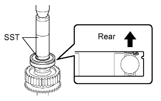 |
Using SST and a press, install a new output shaft rear radial ball bearing.
| 10. INSTALL TRANSFER OUTPUT SHAFT PLATE WASHER |
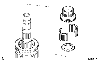 |
Install the transfer output shaft plate washer.
| 11. INSTALL TRANSFER OUTPUT SHAFT FRONT NEEDLE ROLLER BEARING |
| 12. INSTALL TRANSFER CLUTCH HUB |
| 13. INSTALL CENTER DIFFERENTIAL CASE |
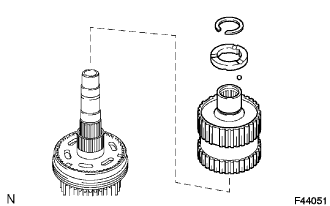 |
Install the center differential case.
| 14. INSTALL TRANSFER OUTPUT SHAFT SPACER BALL |
| 15. INSTALL TRANSFER OUTPUT SHAFT SPACER NO.2 |
| 16. INSTALL TRANSFER LOW PLANETARY RING GEAR HOLE SNAP RING |
Using a snap ring expender, install the snap ring.
| 17. INSTALL DRIVE SPROCKET RADIAL CLEARANCE |
| 18. INSPECT DRIVE SPROCKET THRUST CLEARANCE |
| 19. INSTALL TRANSFER INPUT SHAFT BEARING |
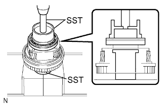 |
Using SST and a press, install a new bearing with the groove facing forward.
| 20. INSTALL TRANSFER LOW PLANETARY GEAR SPLINE PIECE |
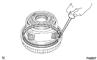 |
Using a screwdriver, install the spline piece and low planetary gear with the snap ring.
| 21. INSTALL TRANSFER LOW PLANETARY GEAR BEARING |
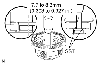 |
Using SST and a press, tap in a new low planetary gear bearing.
| 22. INSTALL TRANSFER INPUT BEARING SHAFT SNAP RING |
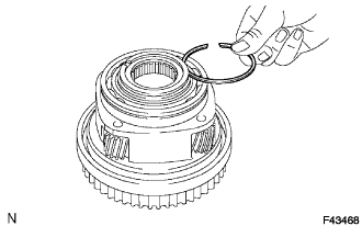 |
Select a snap ring that allows the minimum axial play.
| Mark | Thickness mm (in.) |
| 1 | 1.45 to 1.50 (0.0571 to 0.0591) |
| 2 | 1.50 to 1.55 (0.0591 to 0.0610) |
| 3 | 1.55 to 1.60 (0.0610 to 0.0630) |
| 4 | 1.60 to 1.65 (0.0630 to 0.0650) |
| 5 | 1.65 to 1.70 (0.0650 to 0.0669) |
Using a snap ring expander, install a new snap ring.
| 23. INSTALL TRANSFER NO. 1 INPUT SHAFT SEAL RING |
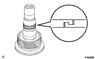 |
Apply gear oil to the oil seal ring.
Engage securely to eliminate clearance as shown in the illustration.
| 24. INSTALL TRANSFER LOW PLANETARY GEAR BEARING |
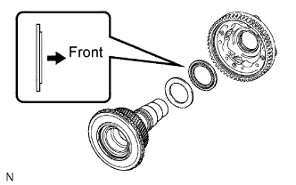 |
Install the transfer low planetary gear bearing.
| 25. INSTALL NO. 1 TRANSFER THRUST BEARING RACE |
| 26. INSTALL TRANSFER INPUT SHAFT |
| 27. INSTALL MANUAL TRANSFER PLANETARY CARRIER WASHER |
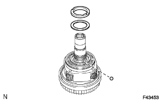 |
Install the manual transfer planetary carrier washer.
| 28. INSTALL TRANSFER INPUT GEAR STOPPER BALL |
| 29. INSTALL TRANSFER INPUT GEAR STOPPER |
| 30. INSTALL TRANSFER INPUT GEAR STOPPER SHAFT SNAP RING |
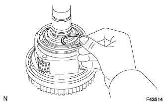 |
Select an input gear stopper shaft snap ring that allows 0.05 to 0.15 mm (0.0020 to 0.0059 in.) axial play.
| Mark | Thickness mm (in.) |
| A | 2.10 to 2.15 (0.0827 to 0.0846) |
| B | 2.15 to 2.20 (0.0846 to 0.0866) |
| C | 2.20 to 2.25 (0.0866 to 0.0886) |
| D | 2.25 to 2.30 (0.0886 to 0.0906) |
| E | 2.30 to 2.35 (0.0906 to 0.0925) |
| F | 2.35 to 2.40 (0.0925 to 0.0945) |
| G | 2.40 to 2.45 (0.0945 to 0.0965) |
| H | 2.45 to 2.50 (0.0965 to 0.0984) |
| J | 2.50 to 2.55 (0.0984 to 0.1004) |
| K | 2.55 to 2.60 (0.1004 to 0.1024) |
| L | 2.60 to 2.65 (0.1024 to 0.1043) |
| M | 2.65 to 2.70 (0.1043 to 0.1063) |
| N | 2.70 to 2.75 (0.1063 to 0.1083) |
| P | 2.75 to 2.80 (0.1083 to 0.1102) |
| Q | 2.80 to 2.85 (0.1102 to 0.1122) |
| R | 2.85 to 2.90 (0.1122 to 0.1142) |
| S | 2.90 to 2.95 (0.1142 to 0.1161) |
| T | 2.95 to 3.00 (0.1161 to 0.1181) |
| U | 3.00 to 3.05 (0.1181 to 0.1201) |
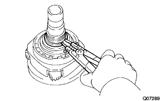 |
Using a snap ring expander, install the new input gear stopper shaft snap ring.
| 31. INSTALL TRANSFER CASE OIL SEAL |
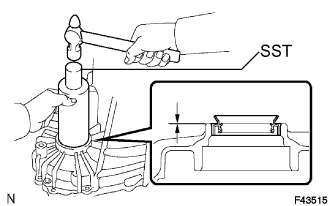 |
Using SST and a hammer, tap in a new oil seal until its surface is flush with the case upper surface.
Coat the lip of the oil seal with MP grease.
| 32. INSTALL LOW PLANETARY GEAR ASSEMBLY WITH INPUT SHAFT SUB-ASSEMBLY |
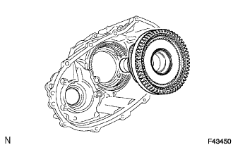 |
Install the low planetary gear assembly with input shaft sub-assembly.
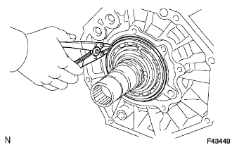 |
Using a snap ring expander, install the shaft snap ring.
| 33. INSTALL TRANSFER OIL PUMP GEAR |
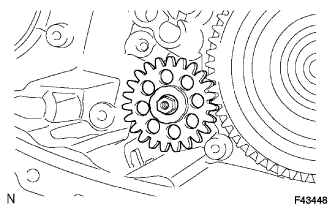 |
Install transfer oil pump gear.
| 34. INSTALL TRANSFER OIL PUMP BODY O-RING |
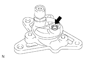 |
Coat a new O-ring with gear oil and install it to the oil pump body.
| 35. INSTALL TRANSFER OIL PUMP BODY SUB-ASSEMBLY |
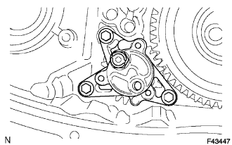 |
Install the oil pump body sub-assembly with the 3 bolts.
| 36. INSTALL TRANSFER CASE MAGNET |
| 37. INSTALL TRANSFER OIL SEPARATOR SUB-ASSEMBLY |
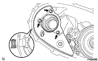 |
Install the oil separator sub-assembly with the 3 bolts.
| 38. INSTALL TRANSFER CASE PLUG |
Install the case plug No. 1 (filler plug) and a new gasket.
| 39. INSTALL TRANSFER CASE PLUG |
Install the case plug (drain plug) and a new gasket.
| 40. INSTALL TRANSFER SHIFT ACTUATOR ASSEMBLY |
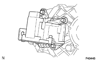 |
Install the shift actuator assembly with the 3 bolts.
Using a screwdriver and hammer, drive in the snap ring.
| 41. INSTALL TRANSFER INPUT GEAR RADIAL BALL BEARING |
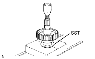 |
Using SST and a press, install a new input gear radial ball bearing.
| 42. INSTALL TRANSFER DRIVEN SPROCKET BEARING |
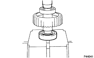 |
Using a press, install a new driven sprocket bearing.
| 43. INSTALL REAR OUTPUT SHAFT SUB-ASSEMBLY, FRONT DRIVE CHAIN AND DRIVEN SPROCKET SUB-ASSEMBLY |
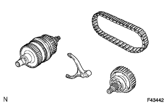 |
Install the rear output shaft sub-assembly, and drive sprocket to the front drive chain.
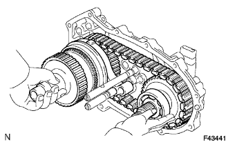 |
Install the rear output shaft sub-assembly, front drive chain and driven sprocket sub-assembly to the rear case.
| 44. INSTALL CTR DIFFERENTIAL LOCK FORK SUB-ASSEMBLY WITH FRONT DRIVE CLUTCH SLEEVE |
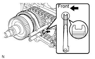 |
Install the CTR differential lock fork sub-assembly and front drive clutch sleeve.
Install the bolt.
Using a screwdriver and hammer, drive in the snap ring.
| 45. INSTALL TRANSFER GEAR SHIFT FORK NO. 2 WITH TRANSFER HIGH AND LOW CLUTCH SLEEVE |
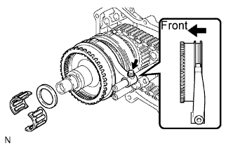 |
Install the gear shift fork No. 2 and high and low clutch sleeve.
Install the bolt.
| 46. INSTALL TRANSFER OUTPUT SHAFT SPACER |
| 47. INSTALL TRANSFER OUTPUT SHAFT FRONT NEEDLE ROLLER BEARING |
| 48. INSTALL TRANSFER CASE REAR |
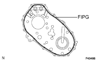 |
Apply FIPG to the case rear, as shown.
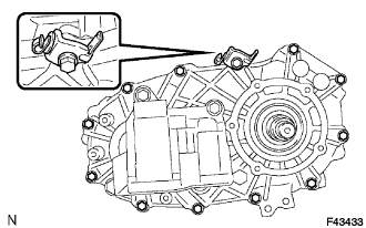 |
Install the clamp and case rear with the 12 bolts.
| 49. INSTALL COLLAR |
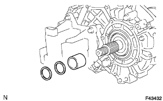 |
Install collar.
| 50. INSTALL TRANSFER OUTPUT WASHER |
| 51. INSTALL TRANSFER EXTENSION HOUSING TYPE T OIL SEAL |
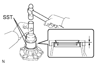 |
Using SST and a hammer, drive in a new oil seal until its surface is flush with the housing upper surface.
Coat the lip of the oil seal with MP grease.
| 52. INSTALL TRANSFER EXTENSION HOUSING SUB-ASSEMBLY REAR |
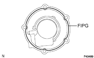 |
Apply FIPG to the extension housing sub-assembly, as shown in the illustration.
Apply sealant to the bolt threads.
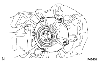 |
Install the extension housing sub-assembly with the 5 bolts.
| 53. INSTALL TRANSFER OUTPUT SHAFT COMPANION FLANGE OIL SEAL |
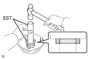 |
Using SST and a hammer, drive in a new oil seal (front side).
Coat the lip of the oil seal with MP grease.
| 54. INSTALL TRANSFER OUTPUT SHAFT COMPANION FLANGE OIL SEAL |
Drive in a new output shaft companion flange oil seal using the same procedure as for the oil seal.
| 55. INSTALL OUTPUT SHAFT COMPANION FLANGE SUB-ASSEMBLY |
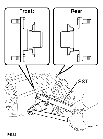 |
Install the companion flange sub-assembly (front side) onto the drive sprocket sub-assembly.
Using SST to hold the companion flange, install a new companion flange lock nut.
Using a chisel and hammer, stake the companion flange lock nut.
| 56. INSTALL OUTPUT SHAFT COMPANION FLANGE SUB-ASSEMBLY |
Using SST, install the companion flange sub-assembly using the same procedure as for the companion flange sub-assembly (rear side).
| 57. INSTALL BREATHER OIL DEFLECTOR |
| 58. INSTALL TRANSFER CASE COVER SUB-ASSEMBLY |
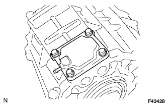 |
Install the case cover sub-assembly with the 4 bolts.
| 59. INSTALL TRANSFER COVER TYPE T OIL SEAL |
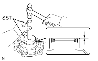 |
Using SST and a hammer, drive in a new oil seal until its surface is flush with the retainer upper surface.
Coat the lip of the oil seal with MP grease.
| 60. INSTALL TRANSFER BEARING RETAINER SUB-ASSEMBLY |
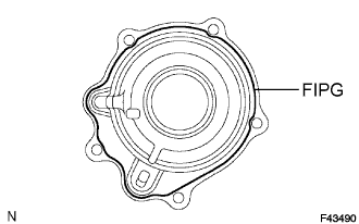 |
Apply FIPG to the front bearing retainer sub-assembly, as shown in the illustration.
Apply sealant to the bolt threads.
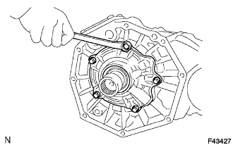 |
Install the front bearing retainer sub-assembly with the 5 bolts.
| 61. INSTALL HOSES |