Home › ENGINE ยท 1GR-FE › LUBRICATION › OIL PUMP

OIL PUMP > REMOVAL

for Preparation Click here


1. REMOVE POWER STEERING LINK ASSEMBLY


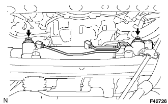
    F042726
  1. Remove the 2 bolts, 2 nuts and power steering link assembly.

    NOTICE:
    The nut has a detent, so never turn the nut, be sure to turn the bolt.

    HINT:
    After the 2 bolts, raise the bolt from the frame, and slide the gear assembly and the bolt as a unit to the position where the bolt can be pulled out, and then remove the bolt.
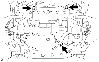
2. REMOVE DIFFERENTIAL CARRIER ASSEMBLY FRONT


    C097020E05
  1. Remove the bolt and separate the front differential breather tube bracket.

  1. Support the front differential with a jack.

  1. Remove the front differential mount nut No. 1.

  1. Remove the 2 front mounting bolts and 2 nuts.

  1. Disconnect the actuator hose and connector.

  1. Lower the jack and remove the front differential assembly.

  1. Remove the 2 bolts and No. 3 front differential support.

  1. Remove the 5 bolts and 2 front differential supports.


3. DRAIN ENGINE COOLANT

CAUTION:
To avoid the danger of being burned, do not remove the radiator cap while the engine and radiator are still hot. Thermal expansion will cause hot engine coolant and steam to blow out from the radiator.


    A070279E01
  1. Remove the service hole cover from the engine under cover.

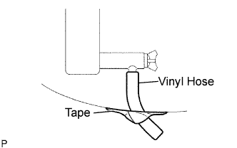
  1. Install a vinyl hose onto the drain on the radiator side.

  1. Fix the vinyl hose with tape.


    A076320E02
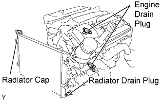
  1. Loosen the 3 drain plugs on the engine and radiator, and drain the coolant.

  1. Remove the radiator cap.

  1. Drain the coolant from the reservoir tank.

  1. Tighten the 3 drain plugs.

    Torque:
    13 N*m{ 130 kgf*cm , 9 ft.*lbf } for the engine

  1. Remove the vinyl hose from the radiator.


4. DRAIN ENGINE OIL


    A076321
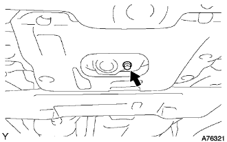
  1. Remove the engine under cover seal No. 3.

  1. Remove the oil pan drain plug and drain the engine oil.

  1. Clean the oil pan drain plug and install it with a new gasket.

    Torque:
    40 N*m{ 408 kgf*cm , 30 ft.*lbf }


5. REMOVE BATTERY


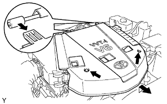
6. REMOVE V-BANK COVER


    A075593E01
  1. Remove the 2 nuts, then remove the V-bank cover.


7. REMOVE RADIATOR SUPPORT SEAL UPPER
  1. Remove the 11 clips and radiator support seal upper.


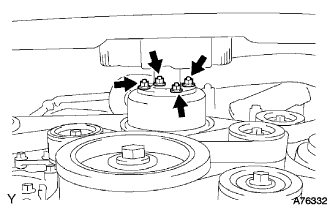
8. LOOSEN FAN WITH FLUID COUPLING


    A076332
  1. Loosen the 4 fluid coupling bolts.


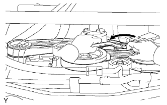
9. REMOVE FAN AND GENERATOR V BELT


    A076441E01
  1. While releasing the belt tension by turning the belt tensioner counterclockwise, remove the V-ribbed belt from the belt tensioner.


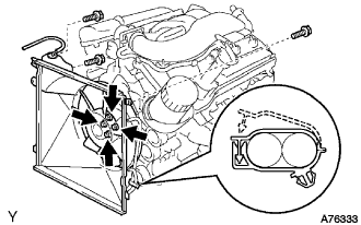
10. REMOVE FAN WITH FLUID COUPLING


    A076333
  1. Unfasten the hose clamp, and then separate the 2 oil cooler hoses from the fan shroud.

  1. Disconnect the radiator reserve tank hose.

  1. Remove the 2 fan shroud bolts and radiator reserve tank bolt.
  1. Remove the 4 fluid coupling nuts, and then remove the fan with fluid coupling and fan shroud together.

  1. Remove the fan pulley.


11. DISCONNECT VENTILATION HOSE NO.2


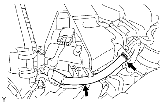
12. REMOVE AIR CLEANER ASSEMBLY


    A075594E01
  1. Disconnect the ventilation hose No. 2.


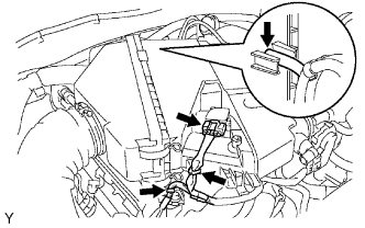
    A075595E01
  1. Disconnect the vacuum hose.

  1. Disconnect the mass air flow meter connector.

  1. Remove the 2 wire harness clamps.


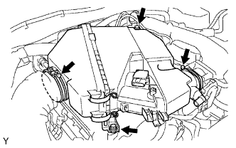
    A075596E01
  1. Loosen the 2 hose clamps.

  1. Remove the 2 bolts, then remove the air cleaner.


13. REMOVE OIL LEVEL GAUGE GUIDE
  1. Remove the oil level gauge.

  1. Remove the bolt and pull out the oil level gauge guide.

  1. Remove the O-ring from the oil level gauge guide.


14. REMOVE WATER INLET


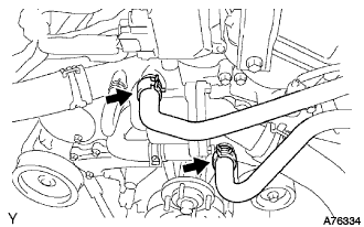
    A076334
  1. Disconnect the 2 oil cooler hoses (with oil cooler).


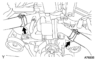
    A076335
  1. Disconnect the 2 radiator hoses.


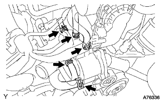
    A076336
  1. Disconnect the 5 water by-pass hoses.


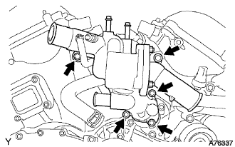
    A076337
  1. Remove the 5 bolts and water inlet.
  1. Remove the O-ring from the water outlet pipe.
  1. Remove the gasket from the water pump.


15. SEPARATE VANE PUMP ASSEMBLY


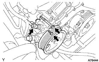
    A076444
  1. Disconnect the P/S oil pressure switch connector.

  1. Remove the 2 bolts, and separate the vane pump.

    NOTICE:
    Do not hit the pulley to other parts when separating the vane pump.

    HINT:
    The vane pump is suspended securely.


16. REMOVE GENERATOR ASSEMBLY


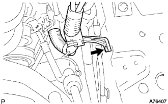
    A076407
  1. Disconnect the wire harness.

    1. Remove the bolt and wire harness stay.

    2. Disconnect the connector from the generator assembly.

    3. Remove the terminal cap and nut.

    4. Disconnect the wire harness from the terminal B.


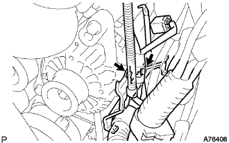
    A076408
  1. Remove the 2 bolts and wire harness clamp bracket from the generator assembly.


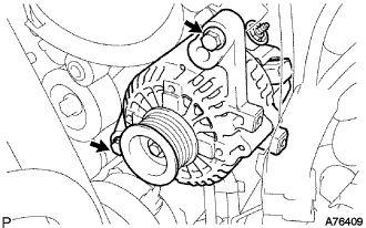
    A076409
  1. Remove the 2 bolts and generator assembly.


17. SEPARATE COOLER COMPRESSOR ASSEMBLY


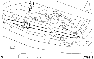
    A076416
  1. Remove the bolt and separate the suction hose sub-assembly.

  1. Disconnect the cooler compressor assembly connector.

  1. Remove the 4 bolts and separate cooler compressor assembly from the V-ribbed belt tensioner assembly.


18. REMOVE V-RIBBED BELT TENSIONER ASSEMBLY


    A076445
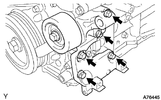
  1. Remove the 5 bolts and V-ribbed belt tensioner.


19. REMOVE NO.2 IDLER PULLEY SUB-ASSEMBLY
  1. Remove the 2 bolts and 2 idler pulleys.


20. REMOVE NO.1 IDLER PULLEY SUB-ASSEMBLY
  1. Remove the bolt and idler pulley.


21. REMOVE CRANKSHAFT PULLEY

HINT:

SST
09213-54015   (91651-60855)
09330-00021  
09950-50013   (09951-05010, 09952-05010, 09953-05020, 09954-05030)


22. REMOVE NO.2 OIL PAN SUB-ASSEMBLY


    A072949
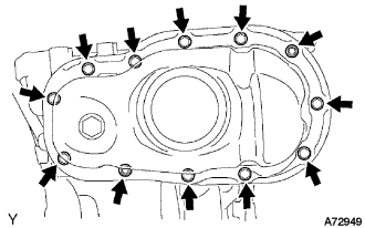
  1. Remove the 10 bolts and 2 nuts.


    A072950E02
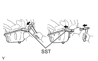
  1. Insert the blade of SST between the oil pan and No. 2 oil pan, and cut off applied sealer and remove the No. 2 oil pan.

    SST
    09032-00100  

    NOTICE:
    1. Be careful not to damage the contact surfaces of the oil pan and No. 2 oil pan.
    2. Be careful not to damage the No. 2 oil pan flange.


23. REMOVE OIL STRAINER SUB-ASSEMBLY


    A072951
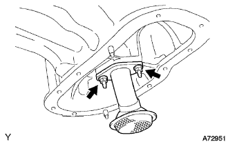
  1. Remove the 2 nuts, oil strainer and gasket.


24. REMOVE OIL PAN SUB-ASSEMBLY


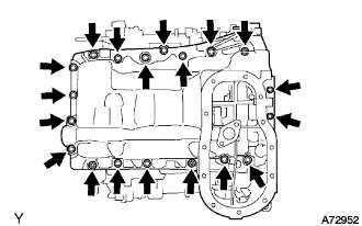
    A072952
  1. Remove the 17 bolts and 2 nuts.

  1. Remove the 4 stud bolts.


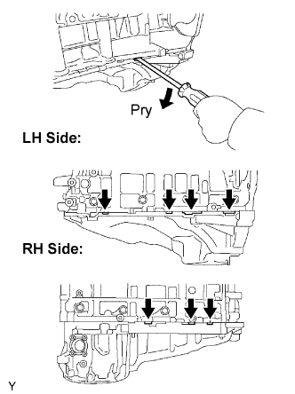
    A072953E01
  1. Using a screwdriver, remove the oil pan by prying between the oil pan and cylinder block as shown in the illustration.

    NOTICE:
    Be careful not to damage the contact surfaces of the cylinder block and oil pan.

  1. Remove the O-ring from the oil pump.


25. REMOVE INTAKE AIR SURGE TANK


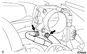
    A076500
  1. Disconnect the 2 water by-pass hoses.


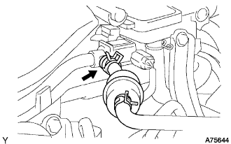
    A075644
  1. Disconnect the fuel vapor feed hose.


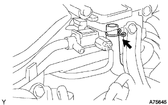
    A075645
  1. Disconnect the ventilation hose.


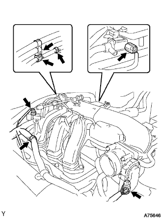
    A075646
  1. Disconnect the 2 VSV connectors.

  1. Disconnect the throttle body with motor connector.

  1. Separate the 3 wire harness clamps and hose clamp.


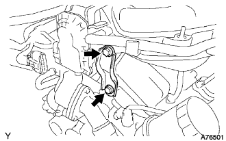
    A076501
  1. Remove the 2 bolts and throttle body bracket.


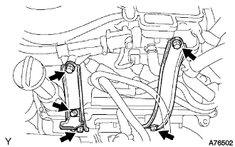
    A076502
  1. Remove the bolt and oil baffle plate.

  1. Remove the 4 bolts and 2 surge tank stays.


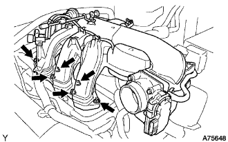
    A075648
  1. Remove the 2 nuts.

  1. Using a socket hexagon wrench 8, remove the 4 bolts, intake air surge tank and gasket.


26. REMOVE IGNITION COIL ASSEMBLY


27. REMOVE CYLINDER HEAD COVER SUB-ASSEMBLY RH


    A072943
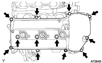
  1. Remove the 10 bolts, 3 seal washers, 2 nuts, cylinder head cover and gasket.


28. REMOVE CYLINDER HEAD COVER SUB-ASSEMBLY LH


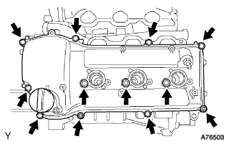
    A076503
  1. Remove the 10 bolts, 3 seal washers, 2 nuts, cylinder head cover and gasket.


29. REMOVE CAMSHAFT TIMING OIL CONTROL VALVE ASSEMBLY
  1. Disconnect the 2 oil control valve connectors.

  1. Remove the 2 bolts and 2 camshaft timing oil control valves.


30. REMOVE VVT SENSOR


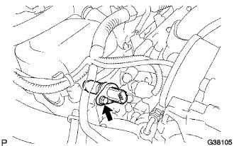
    G038105
  1. RH bank side VVT sensor.

    1. Disconnect the VVT sensor connector.

    2. Remove the bolt and the VVT sensor.


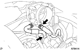
    A076414
  1. LH bank side VVT sensor.

    1. Disconnect the water by-pass hoses No. 4 and No. 5.

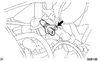
    2. Disconnect the VVT sensor connector.


    3. G038106
    4. Remove the bolt and the VVT sensor.


31. REMOVE OIL FILTER BRACKET SUB-ASSEMBLY
  1. Remove the 3 bolts, 2 nuts, oil filter bracket and gasket.


32. REMOVE TIMING CHAIN COVER SUB-ASSEMBLY


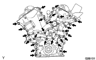
    G038101
  1. Remove the 24 bolts and 2 nuts.


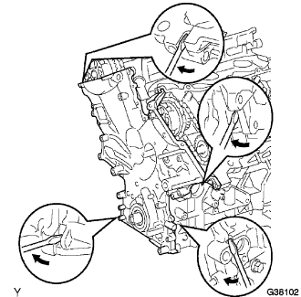
    G038102
  1. Remove the timing chain cover by prying between the timing chain cover and cylinder head or cylinder block with a screwdriver.

    NOTICE:
    Be careful not to damage the contact surfaces of the timing chain cover, cylinder block and cylinder head.

  1. Remove the O-ring from the LH cylinder head.


33. REMOVE TIMING CHAIN COVER OIL SEAL


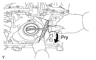
    A076449E01
  1. Using a screwdriver, pry out the oil seal.

    NOTICE:
    Be careful not to damage the oil pump assembly. Wrap the tip of the screwdriver with tape.