 |
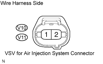
Disconnect the V10 or V11 VSV for air injection system connector.
DTC P1440 Secondary Air Injection Vacuum Switching Valve Circuit Malfunction Bank 1 |
DTC P1443 Secondary Air Injection Vacuum Switching Valve Circuit Malfunction Bank 2 |
| DTC No. | DTC Detection Condition | Trouble Area |
| P1440 | AIV1 terminal voltage becomes less than half of the +B voltage while the VSV for air injection system is not operating. (1 trip detection logic) |
|
| P1443 | AIV2 terminal voltage becomes less than half of the +B voltage while the VSV for air injection system is not operating. (1 trip detection logic) |
|
| Related DTCs | P1440: Secondary air injection system control valve circuit (bank 1) range check P1443: Secondary air injection system control valve circuit (bank 2) range check |
| Required sensors/components | VSV for air injection control |
| Frequency of operation | Continuous |
| Duration | 0.5 seconds |
| MIL operation | Immediate |
| Sequence operation | None |
| The monitor will run whenever these DTCs are not present | None |
| Engine | Running |
| No. 2 air switching valve (bank 1) | Not operating |
| Engine | Running |
| No. 2 air switching valve (bank 2) | Not operating |
| No. 2 air switching valve (bank 1) output terminal level | Low |
| No. 2 air switching valve (bank 2) output terminal level | Low |
| 1.CHECK HARNESS AND CONNECTOR (AIR INJECTION SYSTEM POWER SOURCE) |
|
Disconnect the V10 or V11 VSV for air injection system connector.
Turn the ignition switch ON.
Measure the voltage between terminal 1 of the VSV connector and body ground.
Reconnect the VSV for air injection system connector.
|
| ||||
| OK | |
 |
| 2.CHECK HARNESS AND CONNECTOR (ECM - VSV FOR AIR INJECTION SYSTEM) |
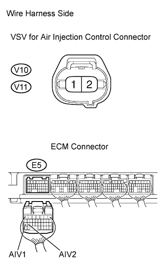 |
Disconnect the E5 ECM connector.
Disconnect the VSV for air injection control connector.
Measure the resistance between the VSV connector and ECM.
| Tester connection | Specified condition |
| AIV1 (E5-27) - V10-2 | Below 1 Ω |
| AIV2 (E5-26) - V11-2 | Below 1 Ω |
Measure the resistance between the VSV connector and body ground.
| Tester connection | Specified condition |
| AIV1 (E5-27) or V10-2 - Body ground | 10 kΩ or higher |
| AIV1 (E5-26) or V11-2 - Body ground | 10 kΩ or higher |
Reconnect the ECM connector.
Reconnect the VSV for air injection control connectors.
|
| ||||
| OK | |
|
| 3.CHECK VSV (RESISTANCE) |
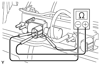 |
Disconnect the V10 or V11 VSV for air injection system connector.
Disconnect the 2 vacuum hoses from the VSV.
Measure the resistance of the VSV terminals.
| Tester Connection | Specified Condition |
| 1 - 2 | 33 to 39 Ω at 20°C (68°F) |
| 1 - Body ground | 10 kΩ or higher |
| 2 - Body ground | 10 kΩ or higher |
Reconnect the VSV for air injection system connector.
Reconnect the vacuum hose.
|
| ||||
| OK | ||
 | ||
| ||
