 |
Disconnect the connector from the sender gauge.
METER / GAUGE SYSTEM > ON-VEHICLE INSPECTION |
| 1. INSPECT SPEEDOMETER |
Check the operation.
Using a speedometer meter tester, check the speedometer indication according to the table below.
| Chassis dynamometer indication | Acceptable range |
| 20 mph | 20.0 to 23.0 mph |
| 40 mph | 40.0 to 43.5 mph |
| 60 mph | 60.0 to 64.0 mph |
| 80 mph | 80.0 to 84.5 mph |
| 100 mph | 100.0 to 105.0 mph |
| Chassis dynamometer indication | Acceptable range Data in ( ) are for reference |
| 20 km/h | (17.5 to 21.5 km/h) |
| 40 km/h | 38.0 to 42.0 km/h |
| 60 km/h | 58.0 to 63.0 km/h |
| 80 km/h | 78.0 to 84.0 km/h |
| 100 km/h | 98.5 to 104.5 km/h |
| 120 km/h | 119.0 to 125.0 km/h |
| 140 km/h | 139.0 to 146.0 km/h |
| 160 km/h | 159.0 to 167.0 km/h |
Check the deviation from the acceptable value of the speedometer indication.
| 2. INSPECT TACHOMETER |
Check operation.
Connect the tune-up test tachometer and start the engine.
Compare the result of the test with the standard indication.
DC 13.5 V, at 25°C (77°F)
| Chassis dynamometer indication (r/min) | Acceptable range (r/min) Data in ( ) are for reference |
| 700 | 630 to 770 |
| 1,000 | (900 to 1,100) |
| 2,000 | (1,850 to 2,150) |
| 3,000 | 2,800 to 3,200 |
| 4,000 | (3,800 to 4,200) |
| 5,000 | 4,800 to 5,200 |
| 6,000 | (5,750 to 6,250) |
| Standard indication (rpm) | Acceptable range (rpm) Data in ( ) are for reference |
| 700 | 630 to 770 |
| 1,000 | (900 to 1,100) |
| 2,000 | (1,850 to 2,150) |
| 3,000 | 2,800 to 3,200 |
| 4,000 | (3,800 to 4,200) |
| 5,000 | 4,800 to 5,100 |
| 6,000 | (5,750 to 6,250) |
| 3. INSPECT FUEL RECEIVER GAUGE |
|
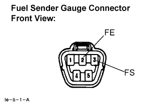
Disconnect the connector from the sender gauge.
Turn the ignition switch ON, then check the position of the receiver gauge needle.
Connect terminals 2 and 3 on the wire harness side connector of the fuel sender gauge.
Turn the ignition switch ON, then check the position of the receiver gauge needle.
| 4. INSPECT FUEL LEVEL WARNING LIGHT |
Disconnect the connector from the sender gauge.
Turn the ignition switch ON, then check that the fuel level needle indicates EMPTY and the fuel level warning light comes on.
| 5. INSPECT SEAT BELT WARNING LIGHT (for Driver Side) |
Turn the ignition switch to ON, and check that the warning light blinks.
Fasten the outer belt to the inner belt and check that the warning light goes off.
Disconnect the connector from the front seat inner belt assembly (driver side), and connect the terminal on the wire harness side connector to body ground.
Turn the ignition switch to ON, and check that the warning light blinks.
| 6. INSPECT LOW ENGINE OIL PRESSURE WARNING LIGHT |
Disconnect the connector from the low oil pressure switch.
Turn the ignition switch ON.
Ground the terminal of the wire harness side connector, then check the low oil pressure warning light.
| 7. INSPECT BRAKE WARNING LIGHT |
Inspect the parking brake warning light.
Disconnect the connector from the parking brake switch.
Turn the ignition switch ON.
Ground the terminal of the wire harness side connector, then check the parking brake warning light.
Inspect the brake fluid level warning light.
Disconnect the connector from the brake fluid level warning switch.
Turn the ignition switch ON.
Connect a terminal to the other terminal of the wire harness side connector, then check the brake fluid level warning switch.
| 8. INSPECT BRAKE FLUID LEVEL WARNING SWITCH |
Remove the reservoir tank cap and strainer.
Disconnect the connector.
Measure the resistance between the terminals.
Use a syphon, etc. to take fluid out of the reservoir tank.
Measure the resistance between the terminals.
Pour the fluid back in the reservoir tank.
| 9. INSPECT SEAT BELT WARNING BUZZER (for Driver Side) |
Check the warning buzzer function.
Turn the ignition switch to ON, and check that the driver's seat belt warning sounds if the driver's seat belt is not fastened.
Check that the buzzer stops in about 4 to 8 seconds.
| 10. INSPECT KEY REMINDER WARNING BUZZER |
Check the warning buzzer function.
Turn the ignition switch off, and check that the key reminder warning sounds when the ignition key is inserted in the key cylinder and the front driver side door is opened.
| 11. INSPECT TRIP METER |
 |
Check the operation.
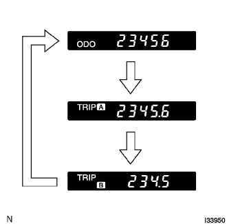
Turn the ignition switch to ON, and check that the mode indication changes in the order of "ODO" → "TRIP A" → "TRIP B" → "ODO" by pressing the trip switch.
Check that the indicated data in "TRIP A" and "TRIP B" is reset by pressing the trip switch for more than 0.5 seconds.
| 12. REMOVE WASHER LEVEL WARNING SWITCH |
Inspect the circuit.
Disconnect the connector from the washer level warning switch.
Turn the ignition switch to ON.
Connect the terminal of the wire harness side connector and body ground, then check the condition of the washer level warning light.
| 13. OIL MAINTENANCE INDICATOR RESETTING PROCEDURE |
| State | Condition | Specified State |
| Blinking | The vehicle runs 4,500 to 5,000 miles after the previous setting | The indicator blinks for 12 seconds after the ignition switch is ON (including 3 seconds for a bulb check) |
| Continuously Illuminated | The vehicle runs over 5,000 miles after the previous setting | The indicator is continuously illuminated after the ignition switch is ON. |
Set the display window to ODO.
Turn the ignition switch off.
While pressing the reset switch, turn the ignition switch ON. Keep pressing the reset switch for at least 5 seconds to complete the reset procedure. Check that the "OIL MAINT" indicator light goes off.