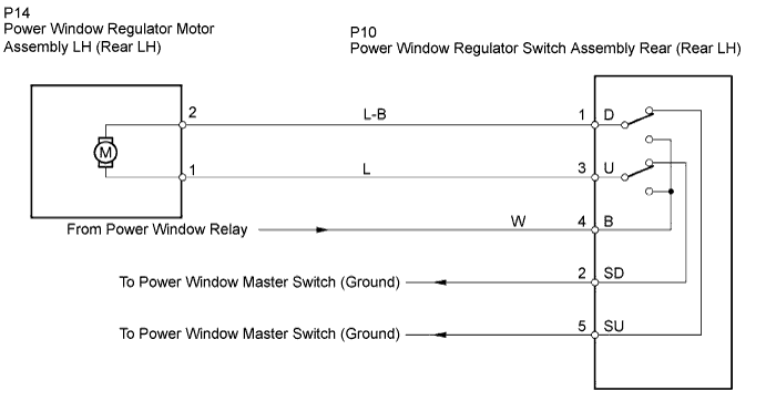
POWER WINDOW CONTROL SYSTEM > Manual Up / Down Function does not Operate on Rear LH Only |
| 1.CHECK WIRE HARNESS (POWER SOURCE) |
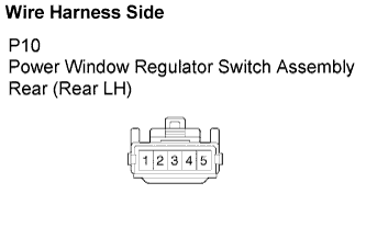 |
Disconnect the P38 regulator switch connector.
Turn the ignition switch ON.
Check the voltage between the terminal 4 of the wire harness side connector and the body ground.
|
| ||||
| OK | |
 |
| 2.INSPECT POWER WINDOW REGULATOR SWITCH (REAR LH) |
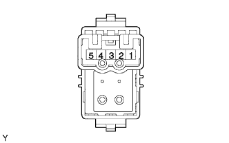 |
Remove the regulator switch.
Check the resistance between the switch terminals when the switch is operated, as shown in the table below.
| Terminal No. | Regulator Switch | Specified Condition |
| 1 - 2, 3 - 4 | UP | Continuity |
| 1 - 2, 3 - 5 | OFF | |
| 1 - 4, 3- 5 | DOWN |
|
| ||||
| OK | |
|
| 3.CHECK WIRE HARNESS (SWITCH - MOTOR) (SWITCH - BODY GROUND) |
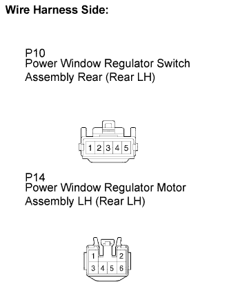 |
Disconnect the P14 motor connector.
Check the resistance between the wire harness side connectors.
| Terminal No. | Specified Condition |
| P10-3 - P14-1 | Continuity |
| P10-1 - P14-2 |
Check the resistance between the P10 regulator switch connector and body ground.
| Terminal No. | Specified Condition |
| P10-1 - Body ground | No continuity |
| P10-3 - Body ground |
|
| ||||
| OK | |
|
| 4.INSPECT POWER WINDOW REGULATOR MOTOR ASSEMBLY LH (REAR LH) |
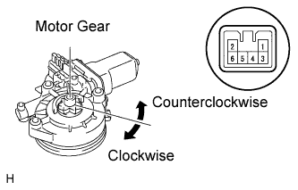 |
Remove the motor.
Apply battery voltage to connector terminals 1 and 2.
Check that the motor smoothly rotates.
| Terminal No. | Specified Condition |
| Battery positive (+) → 2 Battery negative (-) → 1 | Motor gear rotates clockwise |
| Battery positive (+) → 1 Battery negative (-) → 2 | Motor gear rotates counterclockwise |
|
| ||||
| OK | ||
 | ||
| ||
