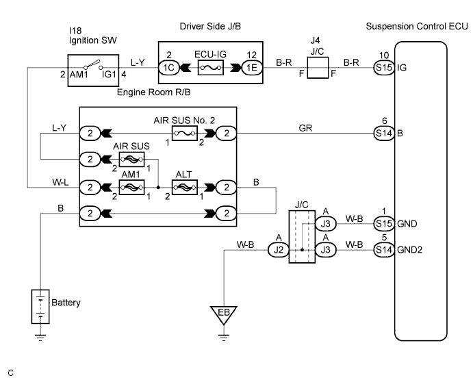
DTC C1774/74 Power Source Circuit |
| DTC No. | DTC Detecting Condition | Trouble Area |
| C1774/74 | The terminal B or IG voltage is detected being below or above a constant voltage for 0.5 seconds. |
|
| 1.INSPECT SOURCE VOLTAGE |
Check the battery voltage.
|
| ||||
| OK | |
 |
| 2.INSPECT FUSE (AIR SUS NO.2) |
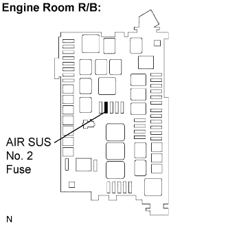 |
Remove the AIR SUS No. 2 fuse from the engine room R/B.
Measure the resistance of the AIR SUS No. 2 fuse.
|
| ||||
| OK | |
|
| 3.INSPECT FUSE (ECU-IG) |
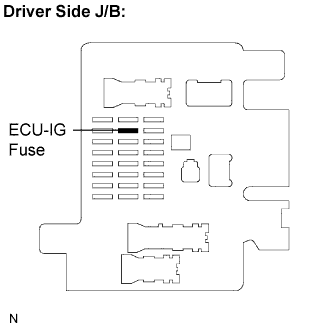 |
Remove the ECU-IG fuse from the driver side J/B.
Measure the resistance of the ECU-IG fuse.
|
| ||||
| OK | |
|
| 4.INSPECT SUSPENSION CONTROL ECU |
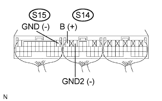 |
Remove the suspension control ECU with connectors still connected.
Turn the ignition switch ON, and measure voltage between terminal S14-6 (B) and S15-1 (GND) and between terminal S14-6 (B) and S14-5 (GND2) of the suspension control ECU connector.
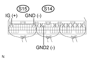 |
Turn the ignition switch ON, measure voltage between terminals S15-10 (IG) and S15-1 (GND) and between terminals S15-10 (IG) and S14-5 (GND2) of the suspension control ECU connector.
|
| ||||
| NG | |
|
| 5.CHECK HARNESS AND CONNECTOR (SUSPENSION CONTROL ECU - BODY GROUND) |
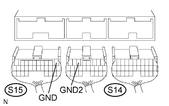 |
Disconnect the suspension control ECU connectors.
Turn the ignition switch ON and measure the resistance between terminal S15-1 (GND) and body ground and between terminal S14-5 (GND2) and body ground.
|
| ||||
| OK | ||
 | ||
| ||
