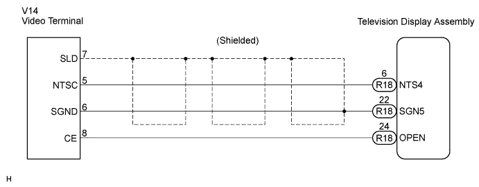
REAR SEAT ENTERTAINMENT SYSTEM > Display Signal Circuit between Video Terminal and Television Display |
| 1.CHECK HARNESS AND CONNECTOR (TELEVISION DISPLAY ASSEMBLY - VIDEO TERMINAL) |
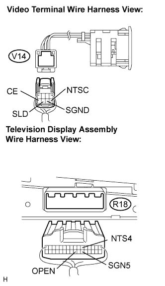 |
Disconnect the connectors from the video terminal and television display assembly.
Measure the resistance according to the value(s) in the table below.
| Tester Connection | Condition | Specified Condition |
| CE - OPEN | Always | Below 1 Ω |
| NTSC - NTS4 | Always | Below 1 Ω |
| SGND - SGN5 | Always | Below 1 Ω |
| NTSC - Body ground | Always | 10 kΩ or higher |
| SGND - Body ground | Always | 10 kΩ or higher |
|
| ||||
| OK | |
 |
| 2.INSPECT VIDEO TERMINAL |
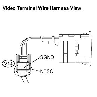 |
Reconnect the video (video adapter) terminal connector.
Measure the waveform according to the table below.
| Tester Connection | Condition | Specified Condition |
| NTSC - SGND | External device is playing | A waveform synchronized with display signals is output |
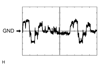 |
Oscilloscope waveform
Terminal: NTSC - Body ground
Setting: 200mV/DIV, 10 μs/DIV
Condition: DVD display is ON.
|
| ||||
| OK | ||
 | ||
| ||
