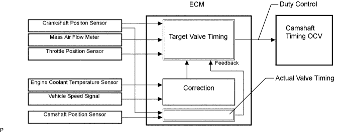
DTC P0010 Camshaft Position "A" Actuator Circuit (Bank 1) |
DTC P0020 Camshaft Position "A" Actuator Circuit (Bank 2) |
| DTC No. | DTC Detection Conditions | Trouble Areas |
| P0010 | Open or short in OCV circuit (1 trip detection logic) |
|
| P0020 | Open or short in OCV circuit (1 trip detection logic) |
|
| Related DTCs | P0010: VVT OCV (Bank 1) range check P0020: VVT OCV (Bank 2) range check |
| Required sensors / components (Main) | VVT OCV |
| Required sensors / components (Related) | - |
| Frequency of operation | Continuous |
| Duration | 1 second |
| MIL operation | Immediate |
| Sequence operation | None |
| The monitor will run whenever these DTCs are not present | None |
| Starter | OFF |
| Ignition switch | ON |
| Time after ignition switch OFF to ON | 0.5 seconds or more |
| One of the following conditions is met: | Condition 1, 2 or 3 |
| 1. All of the following conditions are met: | Condition (a), (b) and (c) |
| (a) Battery voltage | 11 to 13 V |
| (b) Target duty ratio | Less than 70 % |
| (c) Output signal duty ratio | 100 % or more |
| 2. All of the following conditions are met: | Condition (d), (e) and (f) |
| (d) Battery voltage | 13 V or more |
| (e) Target duty ratio | Less than 80 % |
| (f) Output signal duty ratio | 100 % or more |
| 3. All of the following conditions are met: | Condition (g) and (h) |
| (g) Current cut status | Not cut |
| (h) Output signal duty ratio | 3 % or less |
| OCV current | 3 % to 100 % |
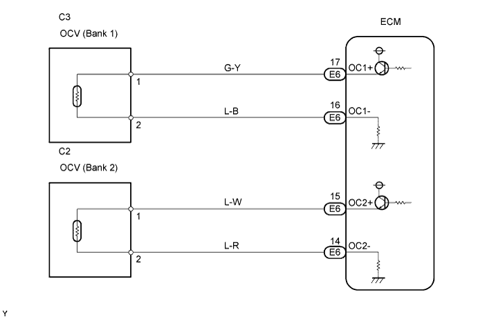
| 1.PERFORM ACTIVE TEST BY INTELLIGENT TESTER (OPERATE OCV) |
Connect the intelligent tester to the DLC3.
Start the engine and turn the tester on.
Warm up the engine and idle it.
Select the following menu items on the tester: DIAGNOSIS / ENHANCED OBD II / ACTIVE TEST / VVT CTRL B1 or VVT CTRL B2.
Check the engine speed while operating the Oil Control Valve (OCV) using the tester.
| Tester Operations | Specified Conditions |
| OCV OFF | Normal engine idle speed |
| OCV ON | Engine idles roughly or stalls (soon after OCV switched from OFF to ON) |
|
| ||||
| NG | |
 |
| 2.INSPECT CAMSHAFT TIMING OIL CONTROL VALVE ASSEMBLY (OCV SIGNAL) |
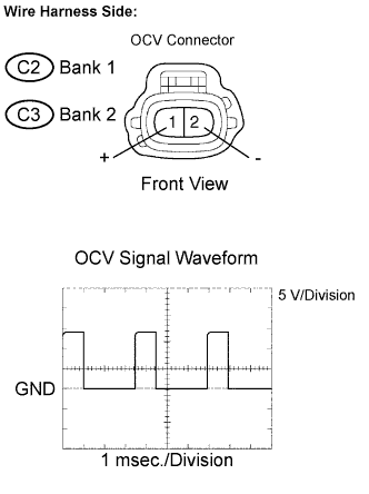 |
Disconnect the C2 or C3 OCV connector.
While idling, check the waveform between the terminals of the C2 or C3 OCV connector using an oscilloscope.
| Tester Connections | Specified Conditions |
| + (C2-1) - - (C2-2) | Correct waveform appears |
| + (C3-1) - - (C3-2) | Correct waveform appears |
Reconnect the OCV connector.
|
| ||||
| NG | |
|
| 3.INSPECT ECM (OCV SIGNAL) |
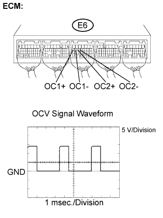 |
Inspect the ECM using an oscilloscope.
While idling, check the waveform between the terminals of the E6 ECM connector.
| Tester Connections | Specified Conditions |
| OC1+ (E6-17) - OC1- (E6-16) | Correct waveform appears |
| OC2+ (E6-15) - OC2- (E6-14) | Correct waveform appears |
|
| ||||
| OK | ||
 | ||
| ||
