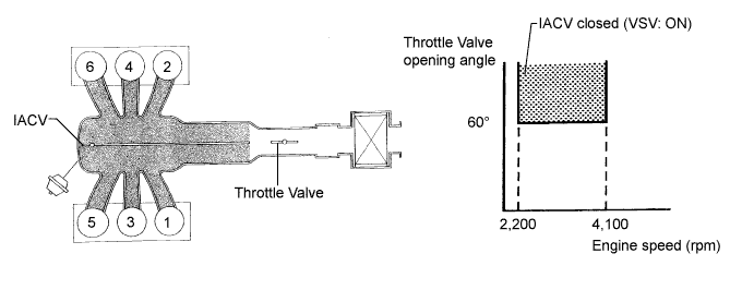
SFI SYSTEM > ACIS Control Circuit |
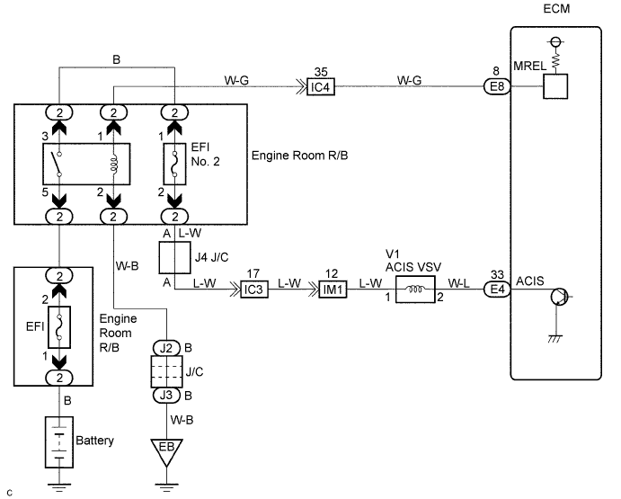
| 1.PERFORM ACTIVE TEST BY INTELLIGENT TESTER (OPERATE VSV FOR ACIS) |
 |
Disconnect the vacuum hose.
Connect the intelligent tester to the DLC3.
Turn the ignition switch to ON and turn the intelligent tester ON.
Select the item: DIAGNOSIS / ENHANCED OBD II / ACTIVE TEST / INTAKE CTL VSV1. Operate the VSV for AICS.
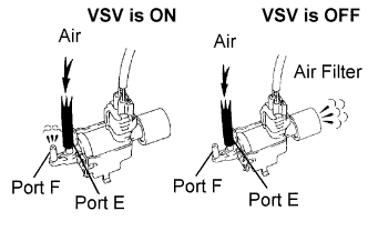
Check the VSV operation when it is operated using the intelligent tester.
| Tester Operation | Specified Condition |
| VSV is ON | Air from port E flows out through port F |
| VSV is OFF | Air from port E flows out through the air filter |
Reconnect the vacuum hose.
|
| ||||
| NG | |
 |
| 2.CHECK VACUUM SWITCHING VALVE (OPERATION) |
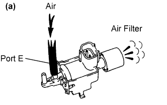 |
Check that air flows from port E to the air filter.
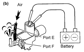 |
Apply battery voltage across the terminals.
Check that air flows from port E to port F.
|
| ||||
| OK | |
|
| 3.CHECK HARNESS AND CONNECTOR (VSV FOR ACIS - ECM, VSV FOR ACIS - EFI RELAY) |
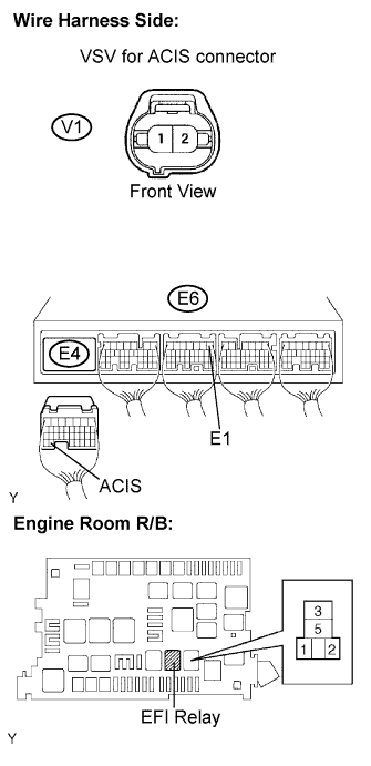 |
Check the wire harness and connectors between the VSV for ACIS and ECM.
Disconnect the V1 VSV for ACIS connector.
Disconnect the E4 ECM connector.
Measure the resistance between the terminals of the VSV for ACIS connector and ECM connector.
| Tester Connections | Specified Conditions |
| VSV for ACIS (V1-1) - ACIS (E4-33) | Below 1 Ω |
| Tester Connections | Specified Conditions |
| VSV for ACIS (V1-1) or ACIS (E4-33) - E1 (E6-1) | 10 kΩ or higher |
Reconnect the VSV for ACIS connector.
Reconnect the ECM connector.
Check the wire harness between the VSV for ACIS and EFI relay.
Disconnect the V1 VSV for ACIS connector.
Remove the EFI fuse from the engine room R/B and J/B.
Measure the resistance of the VSV for ACIS connector and engine room R/B (EFI fuse).
| Tester Connections | Specified Conditions |
| VSV for ACIS (V1-1) - EFI relay (3) | Below 1 Ω |
Reconnect the VSV for ACIS connector.
Reinstall the EFI fuse.
|
| ||||
| OK | |
|
| 4.CHECK VACUUM HOSES |
Check that the vacuum hose is connected correctly.
Check the vacuum hose for looseness and disconnection.
Check the vacuum hose for cracks, holes and damage.
|
| ||||
| OK | |
|
| 5.INSPECT INTAKE AIR CONTROL VALVE (INTAKE AIR SURGE TANK) |
|
| ||||
| OK | ||
 | ||
| ||

