Home › BODY ELECTRICAL › WIPER AND WASHER › WIPER SWITCH

WIPER SWITCH > INSPECTION

for Preparation Click here


1. INSPECT WINDSHIELD WIPER SWITCH ASSEMBLY


    E034825
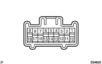
  1. Continuity Check

    1. Check the continuity of each terminal of the connector.

      Front Wiper Switch:
      Switch position
      Tester connection
      Specified condition
      OFF
      16 (+S) - 7 (+1)
      Continuity
      INTO
      16 (+S) - 7 (+1)
      Continuity
      LO
      17 (+B) - 7 (+1)
      Continuity
      HI
      17 (+B) - 8 (+2)
      Continuity

      Rear Wiper Switch:
      Switch position
      Tester connection
      Specified condition
      OFF
      -
      No Continuity
      INTO
      2 (EW) - 13 (C1R)
      Continuity
      ON
      2 (EW) - 10 (+1R)
      Continuity

      Front Washer Switch:
      Switch position
      Tester connection
      Specified condition
      OFF
      -
      No Continuity
      ON
      11 (WF) - 2 (EW)
      Continuity

      Rear Washer Switch:
      Switch position
      Tester connection
      Specified condition
      OFF
      -
      No Continuity
      ON (OFF position side)
      2 (EW) - 12 (WR)
      Continuity
      ON (ON position side)
      2 (EW) - 10 (+1R) - 12 (WR)
      Continuity
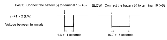


  1. Intermittent Operation Check

    1. Connect the voltmeter (+) terminal to terminal 7 (+1) of the connector, the voltmeter (-) terminal to terminal 2 (EW) of the connector.

    2. Connect the battery (+) to terminal 17 (+B) of the connector, the battery (-) to terminal 2 (EW) and 16 (+S) of the connector.

    3. Turn the wiper switch to INT.

    4. Connect the battery (+) to terminal 16 (+S) of the connector for 5 seconds.


    5. Connect the battery (-) to terminal 16 (+S) of the connector. Operate the intermittent wiper relay and check voltage between terminal 7 (+1) and terminal 2 (EW).


      E056399E32


    I030007E04
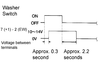
  1. Operation Check (Front Wiper)

    1. Turn the wiper switch to OFF.

    2. Connect the battery (+) to terminal 17 (+B) of the connector, the battery (-) to terminal 16 (+S) and 2 (EW) of the connector.

    3. Connect the voltmeter (+) terminal to terminal 7 (+1) of the connector and the voltmeter (-) terminal to terminal 2 (EW) of the connector. Turn the washer switch to ON and OFF, and check voltage between terminal 7 (+1) and terminal 2 (EW).