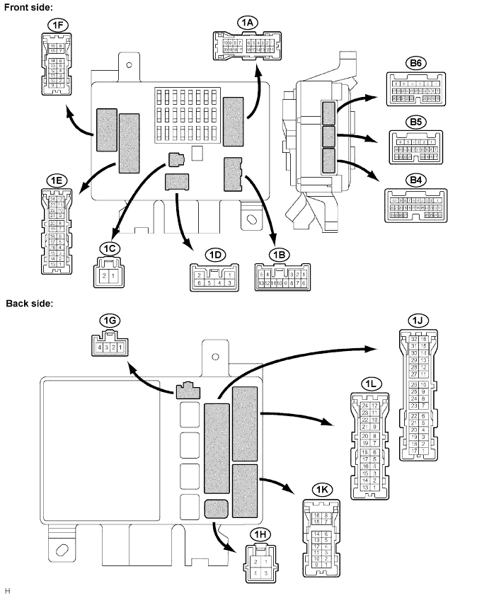
LIGHTING SYSTEM > TERMINALS OF ECU |
| Multiplex Network Body Computer |
| Terminal No. (Symbols) | Wiring color | Condition | Specified condition |
| 1H-2 ←→ Body ground (GND1 ←→ Body ground) | - | Constant | Below 1 V |
| 1K-15, 1L-16 ←→ 1H-2 (LSR ←→ GND1, 2) | - | Rear door lock switch is unlock position | Below 1 V |
| Rear door lock switch is lock position | 10 to 14 V | ||
| 1C-2 ←→ 1H-2 (SIG ←→ GND1, 2) | - | Ignition switch is OFF | Below 1 V |
| Ignition switch is ON | 10 to 14 V | ||
| 1B-4 ←→ 1H-2 (BECU ←→ GND1, 2) | - | Constant | 10 to 14 V |
| 1A-8, 1K-9 ←→ 1H-2 (ILE ←→ GND1, 2) | - | Key cylinder illumination, room light is OFF | Below 1 V |
| Key cylinder illumination, room light is ON | 10 to 14 V | ||
| 1H-2 ←→ Body ground (GND2 ←→ Body ground) | - | Constant | Below 1 V |
| 1B-8 ←→ 1H-2 (HRLY ←→ GND1, 2) | - | Ignition switch is ON and combination switch is OFF | Below 1 V |
| Ignition switch is ON and combination switch is HEAD | 10 to 14 V | ||
| 1C-1 ←→ 1H-2 (TRLY ←→ GND1, 2) | - | Ignition switch is ON and combination switch is OFF | Below 1 V |
| Ignition switch is ON and combination switch is TAIL | 10 to 14 V | ||
| 1D-5 ←→ 1H-2 (ACC ←→ GND1, 2) | - | Ignition switch is OFF | Below 1 V |
| Ignition switch is ON | 10 to 14 V | ||
| B4-3 ←→ 1H-2 (LMRY ←→ GND1, 2) | R ←→ - | Ignition switch is OFF | Below 1 V |
| Ignition switch is ON | 10 to 14 V | ||
| B4-7 ←→ 1H-2 (DRL ←→ GND1, 2) | LG-R ←→ - | Ignition switch is OFF | Below 1 V |
| Ignition switch is ON | 10 to 14 V | ||
| B4-21 ←→ 1H-2 (LSWD ←→ GND1, 2) | W-R ←→ - | Front LH door lock switch is unlock position | Below 1 V |
| Front LH door lock switch is lock position | 10 to 14 V | ||
| B4-23 ←→ 1H-2 (MPX2 ←→ GND1, 2) | BR-R ←→ - | Constant | Signal waveform |
| B4-25 ←→ 1H-2 (PCYL ←→ GND1, 2) | Y ←→ - | Front RH courtesy light is OFF | 10 to 14 V |
| Front RH courtesy light is ON | Below 1 V | ||
| B4-26 ←→ 1H-2 (DCYL ←→ GND1, 2) | W-G ←→ - | Front LH courtesy light is OFF | 10 to 14 V |
| Front LH courtesy light is ON | Below 1 V | ||
| B4-30 ←→ 1H-2 (LSWP ←→ GND1, 2) | B-W ←→ - | Front RH door lock switch is unlock position | Below 1 V |
| Front RH door lock switch is lock position | 10 to 14 V | ||
| B5-6 ←→ 1H-2 (LP ←→ GND1, 2) | W-R ←→ - | Side step light is OFF | Below 1 V |
| Side step light is ON | 10 to 14 V | ||
| B5-11 ←→ 1H-2 (RLCY ←→ GND1, 2) | P-B ←→ - | Rear LH door is closed | 10 to 14 V |
| Rear LH door is open | Below 1 V | ||
| B5-12 ←→ 1H-2 (RRCY ←→ GND1, 2) | P-L ←→ - | Rear RH door is closed | 10 to 14 V |
| Rear RH door is open | Below 1 V | ||
| B5-21 ←→ 1H-2 (LCYL ←→ GND1, 2) | P-G ←→ - | Rear LH courtesy light is OFF | 10 to 14 V |
| Rear LH courtesy light is ON | Below 1 V | ||
| B5-22 ←→ 1H-2 (RCYL ←→ GND1, 2) | L-R ←→ - | Rear RH courtesy light is OFF | 10 to 14 V |
| Rear RH courtesy light is ON | Below 1 V | ||
| B5-23 ←→ 1H-2 (DCTY ←→ GND1, 2) | R-B ←→ - | Front LH door is closed | 10 to 14 V |
| Front LH door is open | Below 1 V | ||
| B5-24 ←→ 1H-2 (PCTY ←→ GND1, 2) | R-Y ←→ - | Front RH door is closed | 10 to 14 V |
| Front RH door is open | Below 1 V | ||
| B6-1 ←→ 1H-2 (HEAD ←→ GND1, 2) | R ←→ - | Ignition switch is ON and combination switch is OFF | 10 to 14 V |
| Ignition switch is ON and combination switch is ON | Below 1 V | ||
| B6-3 ←→ 1H-2 (A ←→ GND1, 2) | G-O ←→ - | Ignition switch is ON and combination switch is OFF | 10 to 14 V |
| Ignition switch is ON and combination switch is AUTO | Below 1 V | ||
| B6-4 ←→ 1H-2 (CLTS ←→ GND1, 2) | Y ←→ - | Cover the sensor with hand → Stop covering | Signal waveform |
| B6-6 ←→ 1H-2 (CLTB ←→ GND1, 2) | L-Y ←→ - | Ignition switch is OFF | Below 1 V |
| Ignition switch is ON | 10 to 14 V | ||
| B6-8 ←→ 1H-2 (TAIL ←→ GND1, 2) | G ←→ - | Ignition switch is ON and combination switch is OFF | 10 to 14 V |
| Ignition switch is ON and combination switch is TAIL | Below 1 V | ||
| B6-21 ←→ 1H-2 (CLTE ←→ GND1, 2) | G-W ←→ - | Constant | Below 1 V |
| Multiplex Network Door ECU: |
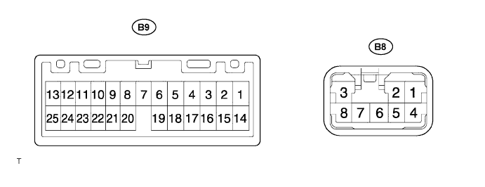
| Terminal No. (Symbols) | Wiring color | Condition | Specified condition |
| B8-1 ←→ B8-3 (MPX2 ←→ GND) | R ←→ W-B | Constant | Signal waveform |
| B8-3 ←→ Body ground (GND ←→ Body ground) | W-B ←→ - | Constant | Below 1 V |
| B8-4 ←→ B8-3 (BDR ←→ GND) | L ←→ W-B | Constant | 10 to 14 V |
| B8-5 ←→ B8-3 (BECU ←→ GND) | L-R ←→ W-B | Constant | 10 to 14 V |
| B8-6 ←→ B8-3 (SIG ←→ GND) | B ←→ W-B | Ignition switch is OFF | Below 1 V |
| Ignition switch is ON | 10 to 14 V | ||
| B9-7 ←→ B8-3 (FULL ←→ GND) | G-Y ←→ W-B | Backdoor is closed | 10 to 14 V |
| Backdoor is open | Below 1 V | ||
| B9-8 ←→ B8-3 (POS ←→ GND) | BR-W ←→ W-B | Backdoor lock switch is unlock position | Below 1 V |
| Backdoor lock switch is lock position | 10 to 14 V | ||
| B9-21 ←→ B8-3 (LSE ←→ GND) | B-R ←→ W-B | Constant | 10 to 14 V |