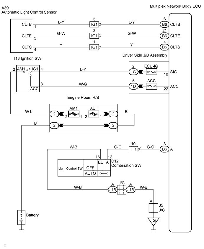
DTC B1244 Light Sensor Circuit Malfunction |
| DTC No. | DTC Detection Condition | Trouble Area |
| B1244 |
|
|
| 1.CHECK LIGHTS |
Check that the headlight and the taillight come on.
|
| ||||
| OK | |
 |
| 2.READ VALUE OF INTELLIGENT TESTER |
Connect the intelligent tester to DLC3.
Turn the ignition switch to ON, and push the intelligent tester main SW ON.
Select the item "AUTO LIGHT SW" in the DATA LIST, and read its value displayed on the intelligent tester.
|
| ||||
| OK | |
|
| 3.INSPECT AUTOMATIC LIGHT CONTROL SENSOR |
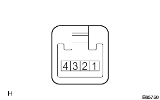 |
Measure voltage between terminals as shown in the chart below.
Check the continuity between terminal 3 (CLTE) and body ground as shown in the chart below.
Using an oscilloscope, check that signal waveform appears between terminals.
| Terminal No. (Symbol) | Tester connection | Condition | Specified condition |
| 1 (CLTB) | 1 - 3 | Constant | 10 to 14 V |
| 3 (CLTE) | 3 - Body ground | Constant | Continuity |
| 4 (CLTS) | 4 - 3 | IG SW ON Dimmer SW AUTO | Signal waveform appears depending on outside brightness |
|
| ||||
| OK | |
|
| 4.CHECK HARNESS AND CONNECTOR (BETWEEN BODY ECU AND AUTOMATIC LIGHT CONTROL SENSOR) |
Check that signal waveform appears between terminals B6-4 (CLTS) and B6-21 (CLTE) of the multiplex network body ECU.
Measure voltage between terminals B6-6 (CLTB) and B6-21 (CLTE) of the multiplex network body ECU.
Check the continuity between terminal B6-21 (CLTE) of the multiplex network body ECU and body ground.
|
| ||||
| OK | ||
 | ||
| ||
| 5.CHECK HARNESS AND CONNECTOR (BETWEEN HEADLIGHT DIMMER SWITCH ASSEMBLY AND BODY ECU) |
Check for open and short circuit in harness and connector.
|
| ||||
| OK | ||
| ||
| ||

