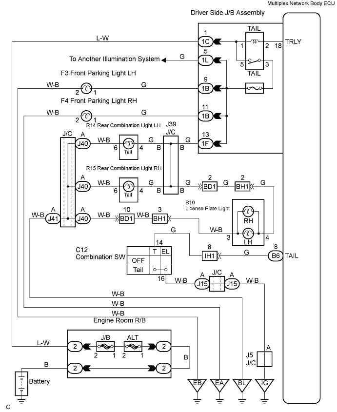
LIGHTING SYSTEM > Taillight Relay Circuit |
| 1.CHECK LIGHTS |
Check the condition A, B or C, when taillight does not light up.
| Condition | Proceed to |
| All | A |
| Parking light only | B |
| Combination light only | C |
|
| ||||
|
| ||||
| A | |
 |
| 2.INSPECT TAILLIGHT RELAY |
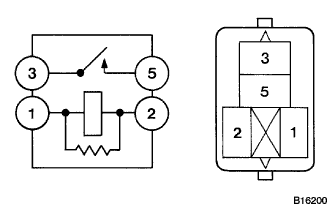 |
Inspect taillight relay continuity.
| Condition | Tester connection | Specified condition |
| Constant | 1 - 2 | Continuity |
| Constant | 3 - 5 | No continuity |
| Apply B+ between terminals 1 and 2 | 3 - 5 | Continuity |
|
| ||||
| OK | |
|
| 3.INSPECT HEADLIGHT DIMMER SWITCH ASSEMBLY |
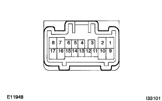 |
Inspect light control switch continuity.
Check that there is continuity between terminals at each switch position as shown in the chart.
| Switch operation | Tester connection | Specified condition |
| OFF | - | No continuity |
| TAIL | 16 - 16 | Continuity |
|
| ||||
| OK | |
|
| 4.CHECK HARNESS AND CONNECTOR (BETWEEN BODY ECU AND HEADLIGHT DIMMER SWITCH ASSEMBLY) |
Check the continuity between terminal B6-8 (TAIL) of the multiplex network body ECU and the headlight dimmer switch assembly.
|
| ||||
| OK | ||
 | ||
| ||
| 5.INSPECT LH HEADLIGHT ASSEMBLY (PARKING LIGHT) |
Check that there is a continuity between terminals of headlight assembly.
|
| ||||
| NG | |
|
| 6.CHECK HARNESS AND CONNECTOR (BETWEEN DRIVER SIDE JUNCTION BLOCK AND LH HEADLIGHT ASSEMBLY) |
Check the continuity between the terminal parking light assembly and driver side junction block.
| Item | Tester connection | Specified condition |
| Parking lamp LH | 1 - 1B-9 | Continuity |
| Parking lamp RH | 1 - 1B-11 | Continuity |
|
| ||||
| OK | ||
| ||
| ||
| 7.INSPECT REAR COMBINATION LIGHT ASSEMBLY LH |
Check that there is a continuity between terminals of rear combination light assembly.
|
| ||||
| NG | |
|
| 8.CHECK HARNESS AND CONNECTOR (BETWEEN DRIVER SIDE J/B AND REAR COMBINATION LIGHT ASSEMBLY) |
Check the continuity terminals 4 of the combination light and 1F-13 of the driver side junction block.
|
| ||||
| OK | ||
| ||
| ||

