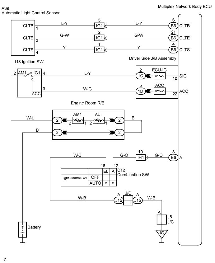
LIGHTING SYSTEM > Automatic Light Control Sensor Circuit |
| 1.CHECK LIGHTS |
Check that headlight and taillight light up.
|
| ||||
| OK | |
 |
| 2.INSPECT HEADLIGHT DIMMER SWITCH ASSEMBLY |
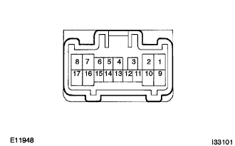 |
Inspect light control switch continuity.
Check that there is a continuity between terminals at each switch position as shown in the chart.
| Switch operation | Tester connection | Specified condition |
| OFF | - | No continuity |
| TAIL | 14 - 16 | Continuity |
| HEAD | 13 - 16 - 14 | Continuity |
| AUTO | 16 - 12 | Continuity |
|
| ||||
| OK | |
|
| 3.INSPECT AUTOMATIC LIGHT CONTROL SENSOR |
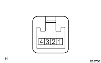 |
Measure voltage between terminals as shown in the chart below.
Check the continuity between terminal 3 (CLTE) and body ground as shown in the chart below.
Using an oscilloscope, check that signal waveform appears between terminals.
| Terminal No. (Symbol) | Tester connection | Condition | Specified condition |
| 1 (CLTB) | 1 - 3 | Constant | 10 to 14 V |
| 3 (CLTE) | 3 - Body ground | Constant | Continuity |
| 4 (CLTS) | 4 - 3 | IG SW ON Dimmer SW AUTO | Signal waveform appears depending on outside brightness |
|
| ||||
| OK | |
|
| 4.CHECK HARNESS AND CONNECTOR (BETWEEN BODY ECU AND AUTOMATIC LIGHT CONTROL SENSOR) |
Check that signal waveform appears between terminals B6-4 (CLTS) and B6-21 (CLTE) of the multiplex network body ECU.
Measure voltage between terminals B6-6 (CLTB) and B6-21 (CLTE) of the multiplex network body ECU.
Check the continuity between terminal B6-21 (CLTE) of the multiplex network body ECU and body ground.
|
| ||||
| OK | ||
 | ||
| ||
