Home › BODY ELECTRICAL › LIGHTING › TURN SIGNAL FLASHER ASSEMBLY

TURN SIGNAL FLASHER ASSEMBLY > ON-VEHICLE INSPECTION

for Preparation Click here


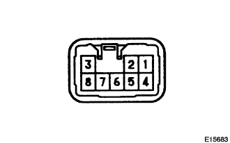
1. INSPECT TURN SIGNAL FLASHER ASSEMBLY (without Daytime Running Light)


    E015683
  1. Measure voltage between terminals as shown in the chart below.

    Standard voltage:

    Tester connection
    Condition
    Specified condition
    1 - Ground
    Turn ignition switch ON
    Battery positive voltage
    1 - Ground
    Turn ignition switch OFF
    No voltage
    4 - Ground
    Constant
    Battery positive voltage
    7 - Ground
    Constant
    Continuity

  1. Connect the connector to the turn signal flasher, and turn the ignition switch to ON, and inspect the wire harness side connector from the back side as shown in the chart.

    Standard voltage:

    Tester connection
    Condition
    Specified condition
    2 - Ground
    Hazard switch OFF → ON
    0 V → 10 to 14 V (60 to 120 time per minutes)
    2 - Ground
    Turn signal switch (right turn) OFF → ON
    0 V → 10 to 14 V (60 to 120 time per minutes)
    3 - Ground
    Hazard switch OFF → ON
    0 V → 10 to 14 V (60 to 120 time per minutes)
    3 - Ground
    Turn signal switch (left turn) OFF → ON
    0 V → 10 to 14 V (60 to 120 time per minutes)
    5 - Ground
    Turn signal switch (left turn) OFF → ON
    10 to 14 V → 0 V
    6 - Ground
    Turn signal switch (right turn) OFF → ON
    10 to 14 V → 0 V
    8 - Ground
    Hazard switch OFF → ON
    10 to 14 V → 0 V


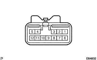
2. INSPECT TURN SIGNAL FLASHER ASSEMBLY (with Daytime Running Light)


    E064832
  1. Measure voltage between terminals as shown in the chart below.

    Standard voltage:

    Tester connection
    Condition
    Specified condition
    9 - Ground
    Constant
    Continuity
    1 - Ground
    Turn ignition switch ON
    Battery positive voltage
    1 - Ground
    Turn ignition switch OFF
    No voltage
    6 - Ground
    Constant
    Battery positive voltage

  1. Connect the connector to the turn signal flasher and turn the ignition switch to ON, and inspect the wire harness side connector from the back side as shown in the chart.

    Standard voltage:

    Tester connection
    Condition
    Specified condition
    2 - Ground
    Hazard switch OFF → ON
    0 V → 10 to 14 V (60 to 120 time per minutes)
    2 - Ground
    Turn signal switch (right turn) OFF → ON
    0 V → 10 to 14 V (60 to 120 time per minutes)
    2 - Ground
    Turn signal switch (right turn) ON → OFF
    10 to 14 V (60 to 120 time per minutes) → 10 to 14 V
    3 - Ground
    Hazard switch OFF → ON
    0 V → 10 to 14 V (60 to 120 time per minutes)
    3 - Ground
    Turn signal switch (right turn) OFF → ON
    0 V → 10 to 14 V (60 to 120 time per minutes)
    4 - Ground
    Hazard switch OFF → ON
    0 V → 10 to 14 V (60 to 120 time per minutes)
    4 - Ground
    Turn signal switch (left turn) OFF → ON
    0 V → 10 to 14 V (60 to 120 time per minutes)
    4 - Ground
    Turn signal switch (left turn) ON → OFF
    10 to 14 V (60 to 120 time per minutes) → 10 to 14 V
    5 - Ground
    Hazard switch OFF → ON
    0 V → 10 to 14 V (60 to 120 time per minutes)
    5 - Ground
    Turn signal switch (left turn) OFF → ON
    0 V → 10 to 14 V (60 to 120 time per minutes)
    7 - Ground
    Turn signal switch (left turn) OFF → ON
    10 to 14 V → 0 V
    8 - Ground
    Turn signal switch (right turn) OFF → ON
    10 to 14 V → 0 V
    10 - Ground
    Hazard switch OFF → ON
    10 to 14 V → 0 V