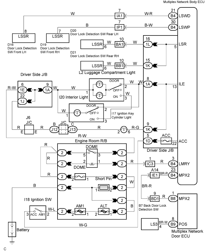
LIGHTING SYSTEM > Illumination Circuit |
| 1.CHECK LIGHTS |
Check the condition A or B, when room light assembly No. 1 does not light up.
| Condition | Proceed to |
| Door Lock → Door Unlock | A |
| IG Switch ACC → OFF | B |
|
| ||||
| A | |
 |
| 2.CHECK DOOR LOCK |
Check which door light does not light up.
| Condition | Proceed to |
| Driver side door | A |
| Passenger side door | B |
| Rear door | C |
| Back door | D |
|
| ||||
|
| ||||
|
| ||||
| A | |
|
| 3.CHECK FRONT DOOR WITH MOTOR LOCK ASSEMBLY LH |
Check the continuity between terminal 8 (LSSR) of front door with motor lock assembly LH and body ground.
| Door lock position | Specified condition |
| Lock | No continuity |
| Unlock | Continuity |
|
| ||||
| OK | |
|
| 4.CHECK HARNESS AND CONNECTOR (BETWEEN BODY ECU AND FRONT DOOR WITH MOTOR LOCK ASSEMBLY) |
Check the continuity between terminal 8 (LSSR) of the front door with motor door lock assembly LH and B4-21 (LSWD) of the multiplex network body ECU.
|
| ||||
| OK | ||
 | ||
| ||
| 5.CHECK FRONT DOOR WITH MOTOR LOCK ASSEMBLY RH |
Check the continuity between terminal 7 (LSSR) of the front door with motor lock assembly RH and body ground.
| Door lock position | Specified condition |
| Lock | No continuity |
| Unlock | Continuity |
|
| ||||
| OK | |
|
| 6.CHECK HARNESS AND CONNECTOR (BETWEEN BODY ECU AND FRONT DOOR WITH MOTOR LOCK ASSEMBLY) |
Check the continuity between terminal 7 (LSSR) of the front door with motor door lock assembly RH and B4-30 (LSWP) of the multiplex network body ECU.
|
| ||||
| OK | ||
| ||
| ||
| 7.CHECK REAR DOOR LOCK |
Check which door light does not light up.
Measure voltage between terminals when unlocking the door.
| Malfunction part | Tester connection | Specified condition |
| Rear door LH | 6 (LSSR) - Body ground | No continuity → Continuity |
| Rear door RH | 6 (LSSR) - Body ground | No continuity → Continuity |
|
| ||||
| OK | |
|
| 8.CHECK HARNESS AND CONNECTOR (BETWEEN DRIVER SIDE JUNCTION BLOCK AND REAR DOOR LOCK) |
Check the continuity between terminals as shown in the chart below.
| Malfunction part | Tester connection | Condition |
| Rear door LH | 1L-16 (LSR) - Rear door lock LH | Continuity |
| Rear door RH | 1K-15 (LSR) - Rear door lock RH | Continuity |
|
| ||||
| OK | ||
| ||
| ||
| 9.CHECK WITH MOTOR BACK DOOR LOCK ASSEMBLY |
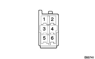 |
Measure voltage between terminal 4 (LS3) of with motor back door lock assembly and body ground.
| Door lock position | Specified condition |
| Lock | No continuity |
| Unlock | Continuity |
|
| ||||
| OK | ||
| ||
| ||
| 10.CHECK DRIVER SIDE JUNCTION BLOCK |
Measure voltage between terminal 1D-5 (ACC) of the driver side junction block and body ground.
| IG SW | Specified condition |
| ACC | 10 to 14 V |
| OFF | Below 1 V |
|
| ||||
| NG | |
|
| 11.CHECK HARNESS AND CONNECTOR (BETWEEN DRIVER SIDE JUNCTION BLOCK AND IGNITION SWITCH) |
Check the continuity between terminal 1D-5 (ACC) of the driver side junction block and the ignition switch assembly.
|
| ||||
| OK | ||
| ||
| ||
| 12.CHECK DRIVER SIDE JUNCTION BLOCK (ILE) |
Measure voltage between terminals as shown in the chart below when turning the ignition switch to OFF.
| Item | Tester connection | Specified condition |
| Transponder key amplifier (Ignition key cylinder light) | 1K-9 (ILE) - Body ground | 10 to 14 V → Below 1 V |
| Room light assembly No. 1, No. 2 (Interior light, Luggage compartment Light) | 1A-8 (ILE) - Body ground | 10 to 14 V → Below 1 V |
|
| ||||
| OK | |
|
| 13.CHECK HARNESS AND CONNECTOR (BETWEEN DRIVER SIDE JUNCTION BLOCK AND LIGHT) |
Disconnect the connector of the driver side junction block.
Check the continuity between terminals as shown in the chart below.
| Item | Tester connection | Specified condition |
| Transponder key amplifier | 1K-9 (ILE) - Transponder key amplifier | Continuity |
| Room light assembly No. 1, No. 2 | 1A-8 (ILR) - Room light assembly | Continuity |
|
| ||||
| OK | |
|
| 14.CHECK TRANSPONDER KEY AMPLIFIER (IGNITION KEY CYLINDER LIGHT) |
Check the continuity between terminals of transponder key amplifier (ignition key cylinder light).
|
| ||||
| OK | |
|
| 15.CHECK ROOM LIGHT ASSEMBLY NO.1 |
Check the continuity between terminals of the room light assembly No. 1.
|
| ||||
| OK | ||
| ||
| ||

