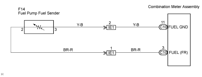
METER / GAUGE SYSTEM > Fuel Receiver Gauge Malfunction |
| 1.CHECK HARNESS OR CONNECTOR |
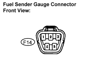 |
Disconnect the F10 connector from the fuel sender gauge assembly.
Check the meter indicator conditions according to the table below.
| Wire connection | Condition | Specified condition |
| 2 - 3 | Short circuit (Ignition switch ON) | Fuel gauge indicates "F" or more (Combination meter) |
Measure the voltage according to the value(s) in the table below.
| Tester connection | Condition | Specified condition |
| 2 - Body ground | Ignition switch ON | 10 to 14 V |
|
| ||||
| OK | |
 |
| 2.INSPECT FUEL SENDER GAUGE ASSEMBLY |
Remove the fuel sender gauge assembly.
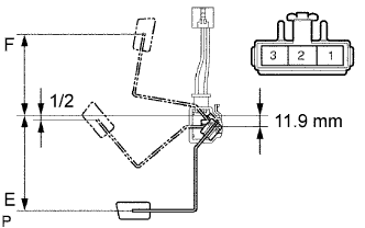 |
Check that the float position is between E and F.
Measure the resistance between terminals 2 and 3 of the connector according to the value(s) in the table below.
| Float level | Float position mm (in.) | Resistance (Ω) |
| F | 88.6 (3.49) +- 3 (0.12) | 4.0 +- 1 |
| 1/2 | 6.4 (0.25) | 59 |
| E | 102.9 (4.05) +- 3 (0.12) | 110.0 +- 2.5 |
|
| ||||
| OK | ||
 | ||
| ||
| 3.CHECK HARNESS AND CONNECTOR (FUEL SENDER GAUGE ASSEMBLY - COMBINATION METER) |
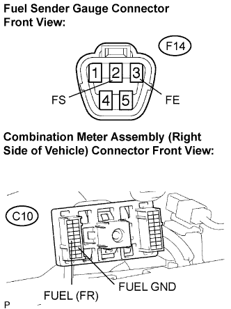 |
Disconnect the C10 and F14 connectors.
Measure the resistance according to the value(s) in the table below.
| Tester connection | Condition | Specified condition |
| C10-3 (FUEL (FR)) - F14-3 | Always | Below 1 Ω |
| C10-11 (FUEL GND) - F14-2 | Always | Below 1 Ω |
|
| ||||
| OK | |
|
| 4.INSPECT INCLINATION SENSOR ASSEMBLY |
Inspect the inclination sensor assembly.
|
| ||||
| OK | ||
| ||
| ||

