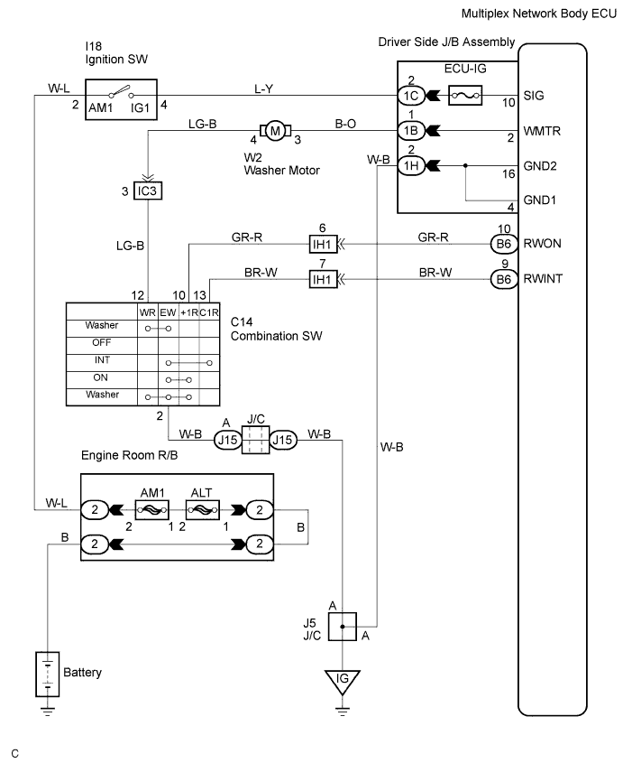
WIPER AND WASHER SYSTEM > Wiper and Washer Switch Circuit |
| 1.CHECK VEHICLE CONDITION |
Check the condition A, B or C, when rear wiper or rear washer system does not operate.
| Condition | Proceed to |
| Rear wiper and washer systems do not operate. | A |
| Rear wiper system does not operate. | B |
| Rear washer system does not operate. | C |
|
| ||||
|
| ||||
| A | |
 |
| 2.INSPECT WINDSHIELD WIPER SWITCH ASSEMBLY |
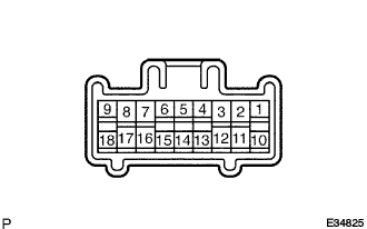 |
Check the continuity of the windshield wiper switch assembly.
| Switch position | Tester connection | Specified condition |
| OFF | - | No Continuity |
| INTO | 2 (EW) - 13 (C1R) | Continuity |
| ON | 2 (EW) - 10 (+1R) | Continuity |
| Switch position | Tester connection | Specified condition |
| OFF | - | No continuity |
| ON (OFF position side) | 2 (EW) - 12 (WR) | Continuity |
| ON (ON position side) | 2 (EW) - 10 (+1R) - 12 (WR) | Continuity |
Check the continuity between the terminals 2 (EW) of windshield wiper switch assembly and body ground.
|
| ||||
| OK | |
|
| 3.INSPECT DRIVER SIDE JUNCTION BLOCK (SIG) |
Measure the voltage between terminals 1C-2 and 1H-2 of driver side junction block when ignition key is ON.
| Switch position | Tester connection | Specified condition |
| OFF | 1C-2 (SIG) - 1H-2 (GND) | Below 1 V |
| ON | 1C-2 (SIG) - 1H-2 (GND) | 10 to 14 V |
|
| ||||
| OK | ||
 | ||
| ||
| 4.INSPECT WINDSHIELD WIPER SWITCH ASSEMBLY |
|
Check the continuity the windshield wiper switch assembly.
| Switch position | Tester connection | Specified condition |
| OFF | - | No Continuity |
| INTO | 2 (EW) - 13 (C1R) | Continuity |
| ON | 2 (EW) - 10 (+1R) | Continuity |
|
| ||||
| OK | |
|
| 5.CHECK MULTIPLEX NETWORK BODY ECU |
Check the continuity terminals multiplex network body ECU and body ground, when rear wiper switch operated.
| Switch position | Tester Connection | Specified Condition |
| INT | B6-9 (RWINT) - Body ground | No continuity → Continuity |
| ON | B6-10 (RWON) - Body ground | No continuity → Continuity |
|
| ||||
| OK | ||
| ||
| ||
| 6.WINDSHIELD WIPER SWITCH ASSEMBLY |
|
Check the continuity the windshield wiper switch assembly.
| Switch position | Tester connection | Specified condition |
| OFF | - | No continuity |
| ON (OFF position side) | 2 (EW) -12 (WR) | Continuity |
| ON (ON position side) | 2 (EW) - 10 (+1R) - 12 (WR) | Continuity |
|
| ||||
| OK | |
|
| 7.INSPECT DRIVER SIDE JUNCTION BLOCK |
Check the continuity terminals driver side junction block and body ground, when rear washer switch operated.
| Switch position | Tester connection | Specified condition |
| ON (OFF position side) | 1B-1 (WMTR) - Body ground | No continuity → Continuity |
| ON (ON position side) | 1B-1 (WMTR) - Body ground | No continuity → Continuity |
|
| ||||
| OK | ||
| ||
| ||

