 |
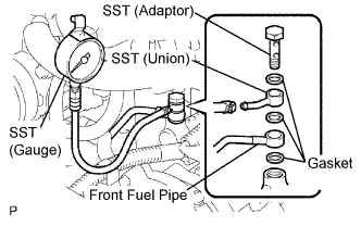
Install the front fuel pipe and SST (pressure gauge) to the delivery pipe with the 3 gaskets and another SST (adaptor).
- SST
- 09268-45014
(09268-41200, 09268-41190, 90405-06167, 09268-41210, 90467-11009)
- Torque:
- 39 N*m{ 400 kgf*cm , 29 ft.*lbf }
KNOCK SENSOR > REMOVAL |
| 1. DISCHARGE FUEL SYSTEM PRESSURE |
Check the battery positive voltage is above 12 V.
Disconnect the negative (-) terminal cable from the battery.
Remove the front fuel pipe from the LH delivery pipe .
|
Install the front fuel pipe and SST (pressure gauge) to the delivery pipe with the 3 gaskets and another SST (adaptor).
Wipe off any splattered gasoline.
Reconnect the negative (-) terminal cable to the battery.
Connect the intelligent tester to the DLC3 (See step 1 in check fuel pump operation).
Measure the fuel pressure.
Disconnect the intelligent tester from the DLC3.
Start the engine.
Measure the fuel pressure at idle.
Stop the engine.
Check that the fuel pressure remains as specified for 5 minutes after the engine has stopped.
After checking the fuel pressure, disconnect the negative (-) terminal cable from the battery and carefully remove the SST to prevent gasoline from splashing.
Reinstall the front fuel pipe to the LH delivery pipe .
Reconnect the negative (-) terminal cable to the battery.
Check for fuel leaks (See step 1 in check fuel pump operation).
| 2. DRAIN ENGINE COOLANT |
Remove the radiator cap.
 |
Remove the service hole cover from the engine under cover No. 1.
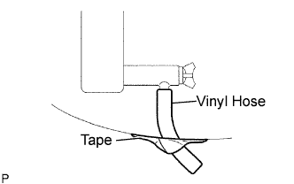
Install a vinyl hose onto the drain on the radiator side.
Fix the vinyl hose with tape.
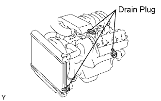 |
Loosen the 3 drain plugs on the engine and radiator, and drain the coolant.
Drain the coolant from the reservoir tank.
Tighten the 3 drain plugs.
Remove the vinyl hose from the radiator.
| 3. REMOVE THROTTLE BODY COVER SUB-ASSEMBLY |
Remove the 2 nuts and throttle body cover sub-assembly.
| 4. REMOVE AIR CLEANER HOSE ASSEMBLY |
Disconnect the vacuum hoses (for the power steering idle-up and fuel pressure regulator) and ventilation hose.
Remove the air cleaner hose assembly.
| 5. DISCONNECT FUEL HOSE |
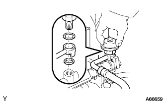 |
Remove the pulsation damper and 2 gaskets.
Disconnect the No. 1 fuel hose.
| 6. DISCONNECT FUEL HOSE NO.2 |
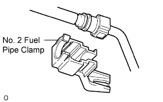 |
Observe the following precautions when disconnecting the fuel tube connector:
Remove the No. 2 fuel pipe clamp.
Check if there is any dirt on the pipe and around the connector before disconnecting them. Clean the dirt away if necessary.
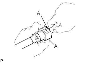 |
Disconnect the connector from the hose while pinching part A with fingers as shown in the illustration.
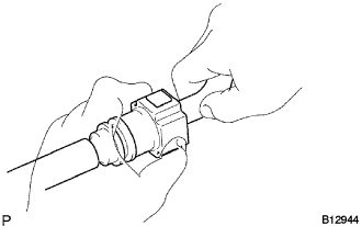 |
When the connector and the pipe are stuck, pinch the fuel pipe with fingers and push the fuel tube connector to the fuel pipe by pressing the release buttons, then pull the connector out from the pipe. Do not use any tool at this time.
Check if there is any dirt or other foreign objects on the seal surface of the disconnected pipe and clean it away.
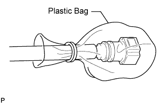 |
Do not damage the disconnected pipe and connector, and prevent intrusion of foreign objects by covering them with a plastic bag.
| 7. DISCONNECT CONNECTORS FROM INTAKE MANIFOLD |
Disconnect the throttle control connector.
Disconnect the VSV connector for EVAP.
Disconnect the 8 injector connectors.
Disconnect the ECT sensor connector.
Disconnect the 2 VSV connectors for the air injection system.
Disconnect the 8 ignition coil connectors.
Disconnect the 2 air fuel ratio sensor connectors.
| 8. DISCONNECT HOSES FROM INTAKE MANIFOLD |
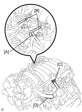 |
Disconnect the vacuum hose [A] from the fuel pressure regulator.
Disconnect the PCV hoses [B] from the PCV valve on the LH cylinder head.
Disconnect the EVAP hose (from the charcoal canister) [C] from the VSV for the EVAP.
Disconnect the 2 vacuum hoses [D] from the VSV for the air injection system.
| 9. REMOVE INTAKE MANIFOLD |
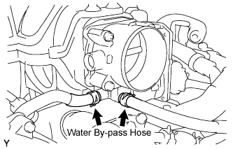 |
Disconnect the 2 water by-pass hoses from the throttle body.
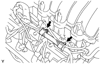 |
Disconnect the 2 wire clamps from the wire clamp bracket on the RH delivery pipe.
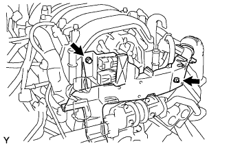 |
Remove the bolt and nut holding the engine wire protector from the intake manifold and cylinder head.
Remove the 2 bolts and ground cables from the RH and LH cylinder heads.
Remove the bolt and V-bank cover bracket from the intake manifold.
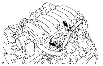 |
Disconnect the engine wire from the engine hanger and wire bracket.
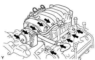 |
Remove the bolt and wire bracket from the intake manifold.
Remove the 6 bolts, 4 nuts, intake manifold assembly and 2 gaskets.
| 10. REMOVE AIR PUMP ASSEMBLY W/ BRACKET |
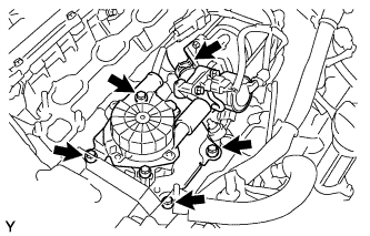 |
Disconnect the No.2 air hose from the air switching valve.
Disconnect the air switching valve connector.
Disconnect the pressure sensor connector for the air injection system.
Remove the 4 bolts and air pump with bracket assembly.
| 11. REMOVE KNOCK SENSOR |
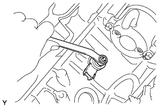 |
Disconnect the 2 knock sensor connectors.
Remove the 2 nuts and 2 knock sensors.