 |
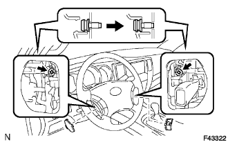
Using a "torx" socket wrench (T30), loosen the 2 "torx" screws until the groove along the screw circumference catches on the screw case.
POWER STEERING LINK > REMOVAL |
| 1. PRECAUTION |
| 2. DISCONNECT BATTERY NEGATIVE TERMINAL |
| 3. PLACE FRONT WHEELS FACING STRAIGHT AHEAD |
| 4. REMOVE STEERING PAD |
|
Using a "torx" socket wrench (T30), loosen the 2 "torx" screws until the groove along the screw circumference catches on the screw case.
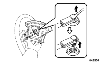 |
Pull out the steering pad from the steering wheel assembly and support the steering pad with one hand as shown in the illustration.
Using a screw driver, disconnect the 2 connectors from the steering pad.
Remove the steering pad.
| 5. REMOVE STEERING WHEEL ASSEMBLY |
 |
without Steering pad switch:
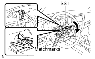
Disconnect the connector.
Remove the steering wheel assembly set nut.
Mark matchmarks on the steering wheel assembly and main shaft assembly.
Set the SST on the steering wheel assembly.
Holding the SST to the monkey spanner and turn the SST, then remove the steering wheel assembly.
| 6. REMOVE STEERING COLUMN COVER LOWER |
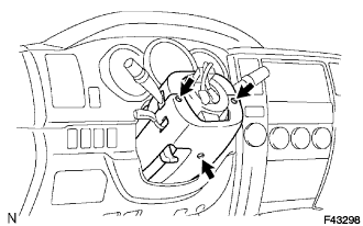 |
Remove the 3 screws and steering column cover lower.
| 7. REMOVE TURN SIGNAL SWITCH ASSEMBLY |
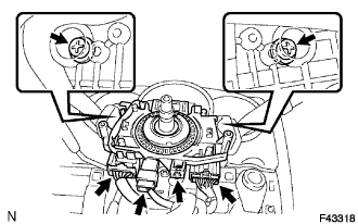 |
Disconnect the 3 connectors.
Remove the 3 screws and turn signal switch assembly.
| 8. REMOVE SPIRAL CABLE |
Disconnect the connectors from the spiral cable.
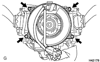 |
Disengage the 4 claws and remove the spiral cable.
| 9. REMOVE FRONT WHEELS |
| 10. REMOVE REAR ENGINE UNDER COVER ASSEMBLY |
Remove the 6 bolts and rear engine under cover assembly.
| 11. REMOVE ENGINE UNDER COVER SUB-ASSEMBLY NO. 1 |
Remove the 4 bolts and engine under cover sub-assembly No. 1.
| 12. REMOVE FRONT STABILIZER BAR |
| 13. SEPARATE TIE ROD END SUB-ASSEMBLY LH |
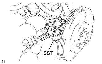 |
Remove the cotter pin and nut.
Using SST, separate the tie rod end from the steering knuckle arm.
| 14. SEPARATE TIE ROD END SUB-ASSEMBLY RH |
| 15. REMOVE STEERING INTERMEDIATE SHAFT SUB-ASSEMBLY NO. 2 |
Mark matchmarks on the power steering gear assembly and steering intermediate shaft sub-assembly No. 2.
Remove the bolt C and intermediate shaft sub-assembly No. 2 from the power steering gear assembly.
| 16. DISCONNECT PRESSURE FEED TUBE ASSEMBLY |
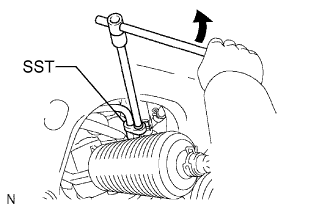 |
Using SST, loosen the flare nut and disconnect the pressure feed tube.
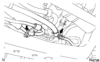 |
Remove the 2 bolts and separate the pressure feed tube assembly from frame sub-assembly.
| 17. DISCONNECT STEERING GEAR OUTLET RETURN TUBE |
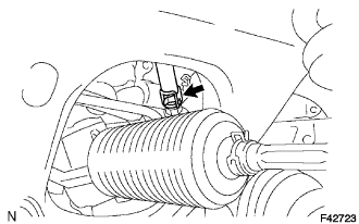 |
Remove the clip and disconnect the return hose.
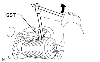 |
Using SST, remove the outlet return tube.
| 18. REMOVE POWER STEERING LINK ASSEMBLY |
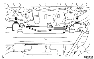 |
Remove the 2 bolts, 2 nuts and power steering link assembly.