 |
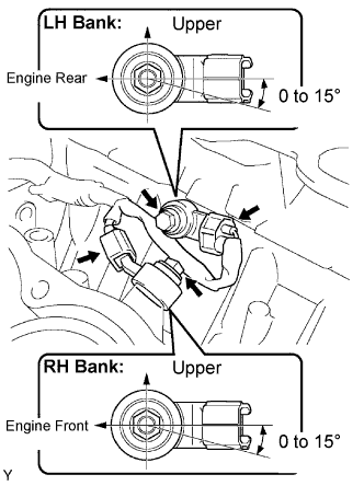
Install the 2 knock sensors with the 2 bolts as shown in the illustration.
- Torque:
- 20 N*m{ 204 kgf*cm , 15 ft.*lbf }
KNOCK SENSOR > INSTALLATION |
| 1. INSTALL KNOCK SENSOR |
|
Install the 2 knock sensors with the 2 bolts as shown in the illustration.
Connect the 2 knock sensor connectors.
| 2. INSTALL WATER OUTLET PIPE NO.1 |
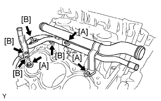 |
Install the 3 bolts [A] and the water outlet pipe.
Install the 4 wire harness clamps [B].
| 3. CONNECT HEATER WATER INLET HOSE A |
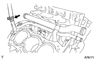 |
Connect the heater water inlet hose A.
| 4. INSTALL CYLINDER HEAD SUB-ASSEMBLY |
Place the cylinder head on the cylinder head gasket.
Install the 8 cylinder head bolts.
Apply a light coat of engine oil to the threads of the cylinder head bolts.
Install the plate washer to the cylinder head bolt.
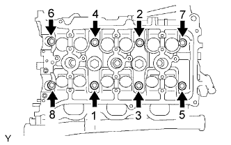 |
Using several steps, tighten each bolt uniformly with a 10 mm bi-hexagon wrench in the sequence as shown in the illustration (Procedure "A").
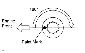 |
Mark the front side of each cylinder head bolt with paint.
Retighten the cylinder head bolts 180° as shown (Procedure "B").
Check that the painted marks are now at 180° opposite to the engine front.
Install the ground cables with the 2 bolts.