Home › ENGINE ยท 1GR-FE › ENGINE CONTROL SYSTEM › KNOCK SENSOR

KNOCK SENSOR > REMOVAL

for Preparation Click here


1. REMOVE CYLINDER HEAD SUB-ASSEMBLY
  1. Remove the 2 bolts and separate the 2 ground cables.


    A076273E03
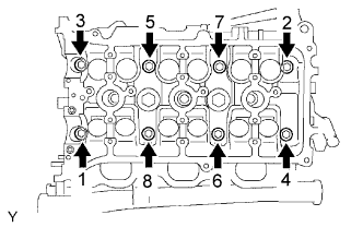
  1. Using several steps, loosen the 8 cylinder head bolts on the cylinder head uniformly with a 10 mm bi-hexagon wrench in the sequence as shown in the illustration. Remove the 8 cylinder head bolts and plate washers.

    NOTICE:
    1. Be careful not to drop the plate washers into the cylinder head.
    2. Cylinder head warpage or cracking could result from removing bolts in incorrect order.


    A076805
  1. Lift the cylinder head from the dowels on the cylinder block, and place the cylinder head on wooden blocks on a bench.

    NOTICE:
    Be careful not to damage the contact surfaces of the cylinder head and cylinder block.

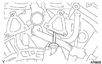
    HINT:
    If the cylinder head is difficult to lift off, pry between the cylinder head and cylinder block with a screwdriver.


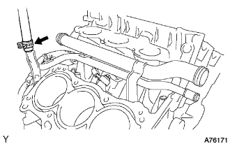
2. DISCONNECT HEATER WATER INLET HOSE A


    A076171
  1. Disconnect the heater water inlet hose A.


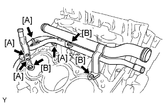
3. REMOVE WATER OUTLET PIPE NO.1


    G038530E01
  1. Remove the 4 wire harness clamps [A].

  1. Remove the 3 bolts [B] and the water outlet pipe.


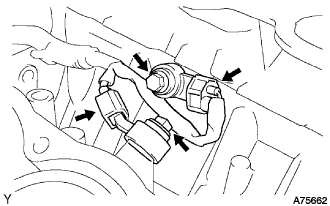
4. REMOVE KNOCK SENSOR


    A075662
  1. Disconnect the 2 knock sensor connectors.

  1. Remove the 2 bolts and the 2 knock sensors.