 |
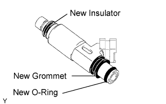
Install a new grommet and insulator to the injector.
FUEL INJECTOR > INSTALLATION |
| 1. INSTALL FUEL INJECTOR ASSEMBLY |
|
Install a new grommet and insulator to the injector.
Check that there is no foreign object or damage to the groove of the O-ring of the injector. Apply gasoline to a new O-ring, and install it to the injector.
Install the injector to the delivery pipe while turning the injector in both ways.
Check that the injector can turn smoothly.
| 2. INSTALL NO. 2 FUEL DELIVERY PIPE SUB-ASSEMBLY |
Install the injector with the delivery pipe to the intake manifold.
Turn the injector in both ways by approximately 45 degrees.
Inserting a spacer between the delivery pipe and the intake manifold, install the delivery pipe with the injector with the 2 nuts.
| 3. INSTALL FUEL DELIVERY PIPE SUB-ASSEMBLY |
Install the injector with the delivery pipe to the intake manifold.
Turn the injector in both ways by approximately 45 degrees.
Inserting a spacer between the delivery pipe and the intake manifold, install the delivery pipe with the injector with the 2 nuts.
| 4. INSTALL FUEL HOSE |
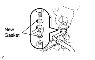 |
Using 2 new gaskets, install the fuel main hose with the fuel pressure pulsation damper.
| 5. INSTALL NO. 1 VACUUM SWITCHING VALVE ASSEMBLY |
| 6. INSTALL NO. 3 FUEL PIPE SUB-ASSEMBLY |
| 7. INSTALL NO. 1 FUEL PIPE SUB-ASSEMBLY |
Install the fuel pipe sub-assembly with the bolts.
Using 4 new gaskets, install the No. 1 fuel pipe sub-assembly with the 2 union bolts.
| 8. INSTALL AIR CLEANER HOSE ASSEMBLY |
| 9. CHECK FOR FUEL LEAKAGE |
When using the intelligent tester
Connect the intelligent tester to the DLC3.
Turn the ignition switch ON and intelligent tester main switch ON.
Select the ACTIVE TEST mode on the intelligent tester.
Please refer to the intelligent tester operator's manual for further details.
 |
When not using the intelligent tester
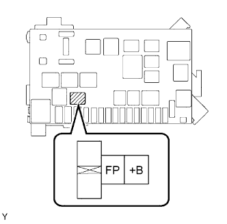
Remove the circuit opening relay.
Using a service wire, connect terminals FP and +B of the relay block.
Turn the ignition switch ON, and check that the fuel pump operates.
Check that there are no fuel leaks after doing maintenance anywhere on the fuel system.
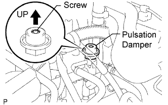 |
Check that the pulsation damper screw rises up when the fuel pump operates.
If operation is not as specified, check the following parts:
Turn the ignition switch OFF.
Disconnect the intelligent tester from the DLC3.
| 10. INSTALL THROTTLE BODY COVER SUB-ASSEMBLY |