 |
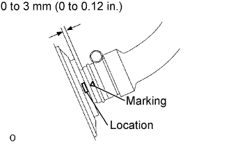
Connect a new fuel tank to filler pipe hose to the fuel tank.
- HINT:
- Make sure that the hose and tank are connected as shown in the illustration.
FUEL TANK > INSTALLATION |
| 1. CONNECT FUEL TANK TO FILLER PIPE HOSE |
|
Connect a new fuel tank to filler pipe hose to the fuel tank.
| 2. INSTALL FUEL TANK BREATHER TUBE SUB-ASSEMBLY |
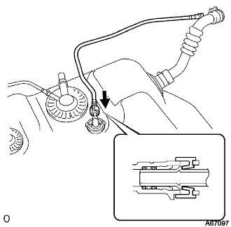 |
Push in the tube connector to the pipe until the connector makes a "click" sound.
| 3. INSTALL FUEL SUCTION WITH PUMP & GAGE TUBE ASSEMBLY |
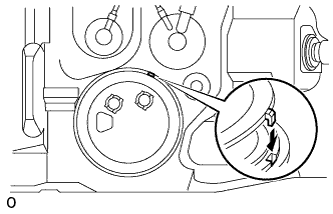 |
Install a new gasket onto the fuel tank.
Set the fuel suction with pump & gage tube assembly to the fuel tank.
Fit the spline of the fuel suction with pump & gage tube assembly into the keyway of the fuel tank.
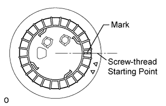 |
Install the retainer.
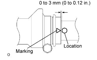
Using a new retainer, align the mark on the retainer with the screw-thread starting point of the fuel tank.
While holding the fuel suction with pump & gage tube assembly, tighten the retainer one complete turn by hand.
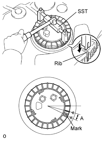 |
Using SST, tighten the retainer one more complete turn, and position the mark on the retainer into range A of the fuel tank.
| 4. INSTALL FUEL TANK MAIN TUBE AND FUEL TANK RETURN TUBE |
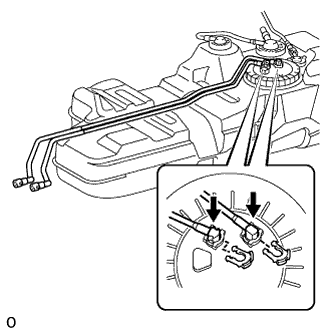 |
Connect the 2 fuel tank tubes with the 2 clips.
| 5. INSTALL FUEL TANK CUSHION |
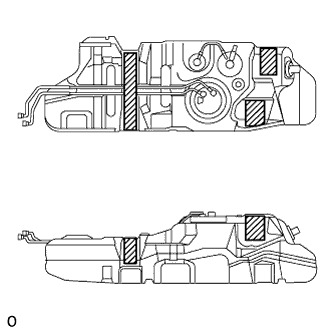 |
Install 3 new fuel tank cushions to the fuel tank.
| 6. INSTALL FUEL TANK ASSEMBLY |
Set a transmission jack to the fuel tank.
Install the fuel tank and 2 fuel tank bands with the 2 bolts.
| 7. CONNECT FUEL TANK BREATHER TUBE SUB-ASSEMBLY |
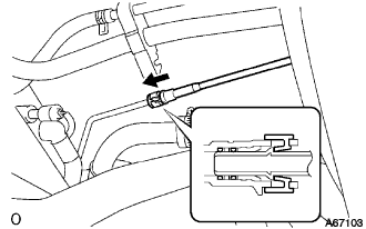 |
Push in the tube connector to the pipe until the connector makes a "click" sound.
| 8. CONNECT FUEL TANK MAIN TUBE AND FUEL TANK RETURN TUBE |
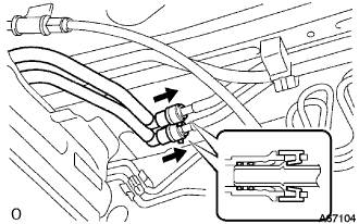 |
Push in the tube connector to the pipe until the connector makes a "click" sound.
| 9. INSTALL NO. 1 FUEL TANK PROTECTOR SUB-ASSEMBLY |
Set a transmission jack to the fuel tank protector.
Install the fuel tank protector with the 6 bolts.
| 10. INSTALL FUEL TANK TO FILLER PIPE HOSE |
 |
Install the fuel tank to filler pipe hose to the fuel filler pipe.
| 11. CHECK FOR FUEL LEAKAGE |
When using the intelligent tester
Connect the intelligent tester to the DLC3.
Turn the ignition switch ON and intelligent tester main switch ON.
Select the ACTIVE TEST mode on the intelligent tester.
Please refer to the intelligent tester operator's manual for further details.
 |
When not using the intelligent tester
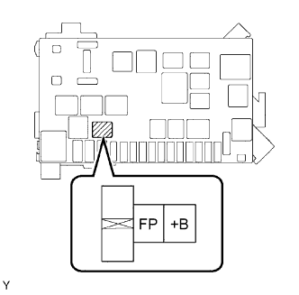
Remove the circuit opening relay.
Using a service wire, connect terminals FP and +B of the relay block.
Turn the ignition switch ON, and check that the fuel pump operates.
Check that there are no fuel leaks after doing maintenance anywhere on the fuel system.
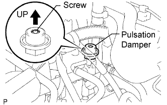 |
Check that the pulsation damper screw rises up when the fuel pump operates.
If operation is not as specified, check the following parts:
Turn the ignition switch OFF.
Disconnect the intelligent tester from the DLC3.
| 12. INSTALL REAR FLOOR SERVICE HOLE COVER |
Connect the connector.
Install the 3 screws and rear floor service hole cover.
Install the rear floor carpet assembly.