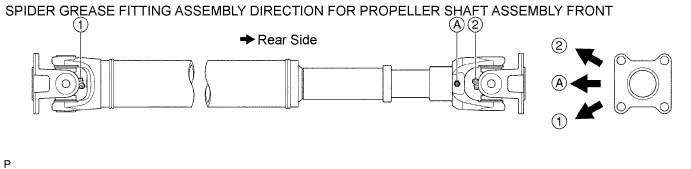
 |
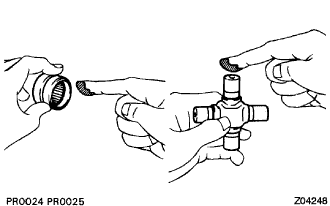
Apply MP grease No. 2 to a new spider and spider bearing.
FRONT PROPELLER SHAFT ASSEMBLY > REASSEMBLY |
| 1. INSTALL FRONT PROPELLER SHAFT UNIVERSAL JOINT SPIDER BEARING |
|
Apply MP grease No. 2 to a new spider and spider bearing.
Fit the spider into the flange yoke.
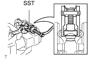 |
Using SST, install the spider bearings on the spider.
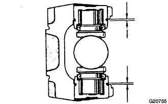
Using SST, adjust both bearings so that the snap ring grooves are at maximum and equal in width.
 |
Install 4 new snap rings of equal thickness which will allow no axial play.
| Parts No. | Thickness mm (in.) | Mark |
| 90520-25039 | 2.28 to 2.30 | 1 |
| 90520-25040 | 2.30 to 2.32 | 2 |
| 90520-25041 | 2.32 to 2.34 | - |
| 90520-25042 | 2.34 to 2.36 | Brown |
| 90520-25043 | 2.36 to 2.38 | Blue |
| 90520-25044 | 2.38 to 2.40 | 6 |
| 90520-25045 | 2.40 to 2.42 | 7 |
| 90520-25046 | 2.42 to 2.44 | 8 |
| 90520-25047 | 2.44 to 2.46 |  |
| 90520-25048 | 2.46 to 2.48 | 10 |
| 90520-25049 | 2.48 to 2.50 | A |
| 90520-25050 | 2.50 to 2.52 | B |
| 90520-25051 | 2.52 to 2.54 | C |
| 90520-25052 | 2.54 to 2.56 | D |
| 90520-25053 | 2.56 to 2.58 | E |
| 90520-25054 | 2.18 to 2.20 | J |
| 90520-25055 | 2.20 to 2.22 | K |
| 90520-25056 | 2.22 to 2.24 | F |
| 90520-25057 | 2.24 to 2.26 | G |
| 90520-25058 | 2.26 to 2.28 | H |
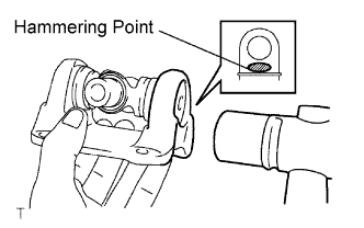 |
Using a hammer, tap the yoke until there is no clearance between the spider bearing outer race and snap ring.
Align the matchmarks on the flange yoke and the sleeve yoke.
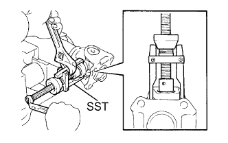 |
Using SST, install the spider bearings on the spider.
Using SST, adjust both bearings so that the snap ring grooves are at maximum and equal in width.
Install new 4 snap rings of equal thickness which will allow no axial play.
| Parts No. | Thickness mm (in.) | Mark |
| 90520-25039 | 2.28 to 2.30 | 1 |
| 90520-25040 | 2.30 to 2.32 | 2 |
| 90520-25041 | 2.32 to 2.34 | - |
| 90520-25042 | 2.34 to 2.36 | Brown |
| 90520-25043 | 2.36 to 2.38 | Blue |
| 90520-25044 | 2.38 to 2.40 | 6 |
| 90520-25045 | 2.40 to 2.42 | 7 |
| 90520-25046 | 2.42 to 2.44 | 8 |
| 90520-25047 | 2.44 to 2.46 | |
| 90520-25048 | 2.46 to 2.48 | 10 |
| 90520-25049 | 2.48 to 2.50 | A |
| 90520-25050 | 2.50 to 2.52 | B |
| 90520-25051 | 2.52 to 2.54 | C |
| 90520-25052 | 2.54 to 2.56 | D |
| 90520-25053 | 2.56 to 2.58 | E |
| 90520-25054 | 2.18 to 2.20 | J |
| 90520-25055 | 2.20 to 2.22 | K |
| 90520-25056 | 2.22 to 2.24 | F |
| 90520-25057 | 2.24 to 2.26 | G |
| 90520-25058 | 2.26 to 2.28 | H |
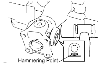 |
Using a plastic hammer, tap the yoke until there is no clearance between the spider bearing outer race and snap ring.
| 2. INSTALL FRONT PROPELLER SHAFT SLIDING SHAFT DUST COVER SUB-ASSEMBLY |
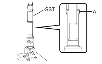 |
Using SST and press, press in a new dust cover.
| 3. INSTALL FR PROPELLER SHAFT UNIVERSAL JOINT SLEEVE YOKE SUB-ASSEMBLY |
 |
Install the grease fitting to the universal joint sleeve yoke.
Apply MP grease to the propeller shaft spline and sleeve yoke sliding surface.
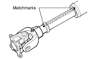
Align the matchmarks on the sleeve yoke propeller shaft.
Install the propeller shaft into the sleeve yoke.
| 4. INSPECT FRONT PROPELLER SHAFT UNIVERSAL JOINT SPIDER BEARING |
| 5. INSPECT PROPELLER SHAFT ASSEMBLY |