Home › ENGINE ยท 1GR-FE › EMISSION CONTROL › EMISSION CONTROL SYSTEM

EMISSION CONTROL SYSTEM > ON-VEHICLE INSPECTION

for Preparation Click here


1. INSPECT AIR-FUEL RATIO COMPENSATION SYSTEM


    A059588E06
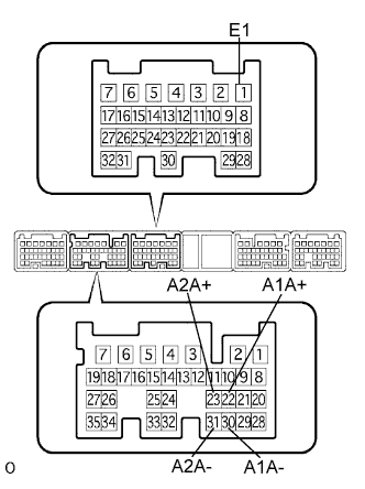
  1. Measure voltage between terminals of the ECM.

    Standard voltage:
    Terminal
    Condition
    Voltage
    A1A+ ←→ E1
    IG switch ON
    3.3 V
    A1A- ←→ E1
    IG switch ON
    3.0 V
    A2A+ ←→ E1
    IG switch ON
    3.3 V
    A2A- ←→ E1
    IG switch ON
    3.0 V

    CAUTION:
    Connect test leads from the back side of the ECM connector.

    HINT:
    Voltage between terminals of the ECM is kept constant regardless of the voltage of A/F sensor.
  1. Connect the intelligent tester to the DLC3.

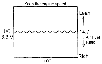
  1. Select "DATA MONITOR" - "A/FS B1 S1", "A/FS B2 S1" and "O2S B1 S2" to display the monitor.

  1. Warm up the A/F sensor with the engine speed at 2, 500 rpm for approx. 2 minutes.


    A052605E02
  1. Keep the engine speed at 2,500 rpm and confirm that the displays of "A/FS B1 S1" and "A/FS B2 S1" are similar to the illustration on the left.

    CAUTION:
    The illustration differs from the real display.

    HINT:
    Only intelligent tester displays the waveform of A/F sensor.

  1. Confirm that the displays of "O2S B1 S2" changes between 0 V to 1 V with the engine speed at 2,500 rpm.


2. INSPECT FUEL CUT OFF RPM
  1. Increase the engine speed to at least 3,500 rpm.

  1. Use a sound scope to check for injector operating noise.

  1. Check that when the throttle lever is released, injector operation noise stops momentarily and then resumes.

    Fuel cut off rpm:
    2,500 rpm

    Fuel return rpm:
    1,200 rpm


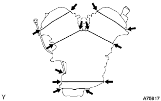
3. VISUALLY INSPECT HOSES, CONNECTIONS AND GASKETS


    A075917
  1. Check for cracks, leaks or damage.

    HINT:
    Separation of the engine oil dipstick, oil filter cap, PCV hose, etc. may causes an engine failure or engine malfunctions. Disconnection, looseness or cracks in the parts of the air induction system between the throttle body and cylinder head will allow air suction and cause an engine failure or engine malfunctions.


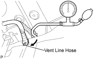
4. CHECK AIR TIGHTNESS IN FUEL TANK AND FILLER PIPE


    A067134E01
  1. Disconnect the vent line hose from the fuel tank .

  1. Apply pressure to the fuel tank and make the internal pressure of the air pressure 4 kPa (41 gf/cm2, 0.58 psi).

  1. Check that the internal pressure in the fuel tank is maintained for 1 minute.

  1. Check the connections for each hose and pipe.

  1. Check the installed parts on the fuel tank. If there is no abnormality, replace the fuel tank and filler pipe.

  1. Reconnect the vent line hose to the fuel tank.


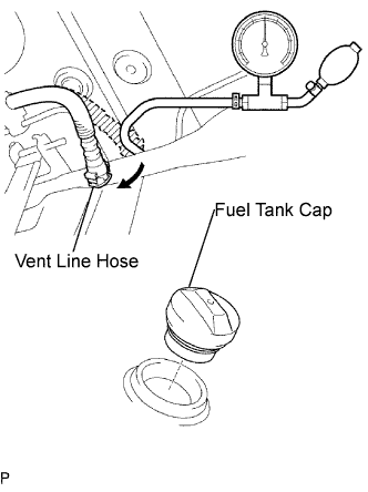
5. INSPECT FUEL CUT OFF VALVE AND FILL CHECK VALVE


    A067135E01
  1. Fill the fuel tank with fuel enough.

  1. Disconnect the vent line hose from the fuel tank .

  1. Apply 4 kPa (41 gf/cm2, 0.58 psi) to the vent port of the fuel tank.

  1. Remove the fuel tank cap, and check that the pressure inside the tank drops.
    If pressure does not drop, replace the fuel tank assembly.

  1. Reconnect the vent line hose to the fuel tank.


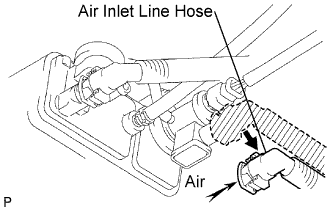
6. CHECK AIR INLET LINE


    A067136E02
  1. Disconnect the air inlet line hose from the charcoal canister .

  1. Check that there is ventilation in the air inlet line.

  1. Reconnect the air inlet line hose to the charcoal canister.


7. INSPECT VAPOR PRESSURE SENSOR


    B016532E01
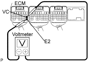
  1. Inspect the power source voltage of the vapor pressure sensor.

    1. Turn the ignition switch ON.

    2. Using a voltmeter, measure the voltage between connector terminals VC and E2 on the wiring harness side of the ECM.

      Voltage:
      4.5 to 5.5 V

    3. Turn the ignition switch OFF.


    A075946E01
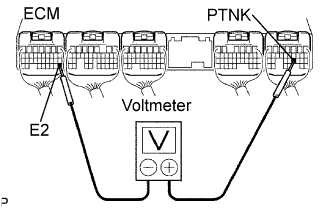
  1. Inspect the power output of the vapor pressure sensor.

    1. Turn the ignition switch ON.

    2. Remove the fuel tank cap.

    3. Using a voltmeter, measure the voltage between connector terminals PTNK and E2 on the wiring harness side of the ECM.

      Voltage:
      3.0 to 3.6 V

    4. Reinstall the fuel tank cap.