
AIR CONDITIONING SYSTEM > TERMINALS OF ECU |
| Air conditioning amplifier |
| Symbols (Terminals No.) | Wiring Color | Condition | Specification |
| IG - GND (A16-1 - A16-5) | Y-R - W-B | Ignition switch: ON | 10 to 14 V |
| +B - GND (A16-2 - A16-5) | W-R - W-B | Always | 10 to 14 V |
| BLW - GND (A16-3 - A16-5) | LG-B - W-B | Ignition switch: ON Blower motor: Operating | Pulse generation (See waveform 1) |
| LIN1 (A16-4) | L-B | Heater control panel communication circuit | - |
| GND - Body ground (A16-5 - Body ground) | W-B - Body ground | Always | Below 1.0 Ω |
| SG - Body ground (A16-6 - Body ground) | Y-G - Body ground | Always | Below 1.0 Ω |
| TWI - GND (A16-7 - A16-5) | L-B - W-B | Ignition switch: ON | Pulse generation (See waveform 2) |
| SPD - GND (A16-8 - A16-5) | V-R - W-B | Ignition switch: ON Turn propeller shaft slowly | 0 - 4.5 to 5.5 V (Voltage is generated intermittently) |
| TSDR - S5 (A16-12 - A17-1) (*1) | R - P (*1) | Ignition switch: ON, Solar sensor subject to electric light | 4.0 to 5.5 V |
| TSDR - S5 (A16-12 - A17-1) (*1) | R - P (*1) | Ignition switch: ON, Solar sensor covered by a cloth | Below 1.0 V |
| TS - S5 (A16-12 - A17-1) (*2) | V-G - P (*2) | Ignition switch: ON, Solar sensor subject to electric light | 4.0 to 5.5 V |
| TS - S5 (A16-12 - A17-1) (*2) | V-G - P (*2) | Ignition switch: ON, Solar sensor covered by a cloth | Below 1.0 V |
| TR - SG (A16-15 - A16-6) | V-Y - Y-G | Ignition switch: ON, Room temp.: 25°C (77°F) | 1.35 to 1.75 V |
| TR - SG (A16-15 - A16-6) | V-Y - Y-G | Ignition switch: ON, Room temp.: 40°C (104°F) | 0.85 to 1.25 V |
| TPI - SG (A16-16 - A16-6) | P-B - Y-G | Ignition switch: ON Set air intake: RECIRCULATION | 3.5 to 4.5 V |
| TPI - SG (A16-16 - A16-6) | P-B - Y-G | Ignition switch: ON Set air intake: FRESH | 0.5 to 1.8 V |
| TPO - SG (A16-17 - A16-6) | LG-R - Y-G | Ignition switch: ON, Set air flow: FACE | 3.5 to 4.5 V |
| TPO - SG (A16-17 - A16-6) | LG-R - Y-G | Ignition switch: ON, Set air flow: DEF | 0.5 to 1.8 V |
| ACT - GND (A16-18 - A16-5) | BR-W - W-B | Start engine Blower speed: LO Magnetic clutch: Engaged | 10 to 14 V |
| ACT - GND (A16-18 - A16-5) | BR-W - W-B | Start engine Blower speed: LO Magnetic clutch: Not engaged | Below 1.0 V |
| LOCK - GND (A16-19 - A16-5) | W-G - W-B | Engine running: Idle speed A/C system: Operate speed | Pulse generation (See waveform 3) |
| HR - GND (A16-21 - A16-5) | L - W-B | Ignition switch: ON, Blower switch: ON | Below 1.0 V |
| HR - GND (A16-21 - A16-5) | L - W-B | Ignition switch: ON, Blower switch: OFF | 10 to 14 V |
| TAM - SG (A16-22 - A16-6) | GR - Y-G | Ignition switch: ON, Ambient temp.: 25°C (77°F) | 1.35 to 1.75 V |
| TAM - SG (A16-22 - A16-6) | GR - Y-G | Ignition switch: ON, Ambient temp.: 40°C (104°F) | 0.85 to 1.25 V |
| TPPA - SG (A16-23 - A16-6) (*1) | L-W - Y-G | Ignition switch: ON Set passenger side temp.: Max. COLD | 3.5 to 4.5 V |
| TPPA - SG (A16-23 - A16-6) (*1) | L-W - Y-G | Ignition switch: ON Set passenger side temp.: Max. HOT | 0.5 to 1.5 V |
| TE - SG (A16-24 - A16-6) | G - Y-G | Ignition switch: ON Evaporator temp.: 0°C (32°F) | 2.0 to 2.4 V |
| TE - SG (A16-24 - A16-6) | G - Y-G | Ignition switch: ON Evaporator temp.: 15°C (59°F) | 1.4 to 1.8 V |
| TPDR - SG (A16-25 - A16-6) (*1) | L-O - Y-G | Ignition switch: ON Set (driver side *1) temp.: Max. COLD | 3.5 to 4.5 V |
| TPDR - SG (A16-25 - A16-6) (*1) | L-O - Y-G | Ignition switch: ON Set (driver side *1) temp.: Max. HOT | 0.5 to 1.5 V |
| TP - SG (A16-25 - A16-6) (*2) | L-O - Y-G | Ignition switch: ON Set (driver side *1) temp.: Max. COLD | 3.5 to 4.5 V |
| TP - SG (A16-25 - A16-6) (*2) | L-O - Y-G | Ignition switch: ON Set (driver side *1) temp.: Max. HOT | 0.5 to 1.5 V |
| TSPA - S5 (A16-26 - A17-1) (*1) | B-O - P | Ignition switch: ON, Solar sensor subject to electric light | 4.0 to 5.5 V |
| TSPA - S5 (A16-26 - A17-1) (*1) | B-O - P | Ignition switch: ON, Solar sensor covered by a cloth | Below 1.0 V |
| S5 - SG A17-1 - A16-6) | P - Y-G | Ignition switch: ON | 4.5 to 5.5 V |
| AOF - GND (A17-3 - A16-5) | LG-R - W-B | Ignition switch: ON, Set air flow: FACE | 10 to 14 V |
| AOF - GND (A17-3 - A16-5) | LG-R - W-B | Ignition switch: ON, Set air flow: Except FACE | Below 1.0 V |
| AOD - GND A17-4 - A16-5) | LG - W-B | Ignition switch: ON, Set air flow: DEF | 10 to 14 V |
| AOD - GND A17-4 - A16-5) | LG - W-B | Ignition switch: ON, Set air flow: Except DEF | Below 1.0 V |
| AIR - GND (A17-5 - A16-5) | P-L - W-B | Ignition switch: ON Set air intake: RECIRCULATION | 10 to 14 V |
| AIR - GND (A17-5 - A16-5) | P-L - W-B | Ignition switch: ON, Set air intake: FRESH | Below 1.0 V |
| AIF - GND (A17-6 - A16-5) | P-G - W-B | Ignition switch: ON, Set air intake: FRESH | 10 to 14 V |
| AIF - GND (A17-6 - A16-5) | P-G - W-B | Ignition switch: ON Set air intake: RECIRCULATION | Below 1.0 V |
| AC1 - GND (A17-7 - A16-5) | GR-G - W-B | Start engine Blower speed: LO Magnetic clutch: Engaged | Below 1.0 V |
| AC1 - GND (A17-7 - A16-5) | GR-G - W-B | Start engine Blower speed: LO Magnetic clutch: Not engaged | 10 to 14 V |
| PSW - GND (A17-9 - A16-5) | LG-R - W-B | Start engine Operate A/C system Refrigerant pressure: Abnormal pressure (More than 3,140 kPa and less than 196 kPa) | Below 1.0 V |
| PSW - GND (A17-9 - A16-5) | LG-R - W-B | Start engine Operate A/C system Refrigerant pressure: Normal pressure (Less than 3,140 kPa and less than 196 kPa) | 10 to 14 V |
| MGC - GND (A17-10 - A16-5) | BR-Y - W-B | Engine running: Idle speed A/C system: Operate Magnetic clutch: Not engaged | 10 to 14 V |
| MGC - GND (A17-10 - A16-5) | BR-Y - W-B | Engine running: Idle speed A/C system: Operate Magnetic clutch: Engaged | Below 1.0 V |
| AMHDR - GND (A17-14 - A16-5) (*1) | V-W - W-B | Ignition switch: ON Set (driver side *1) temp.: Max. HOT | 10 to 14 V |
| AMHDR - GND (A17-14 - A16-5) (*1) | V-W - W-B | Ignition switch: ON Set (driver side *1) temp.: Max. COLD | Below 1.0 V |
| AMH - GND (A17-14 - A16-5) (*2) | V-W - W-B | Ignition switch: ON Set (driver side *1) temp.: Max. HOT | 10 to 14 V |
| AMH - GND (A17-14 - A16-5) (*2) | V-W - W-B | Ignition switch: ON Set (driver side *1) temp.: Max. COLD | Below 1.0 V |
| AMHPA - GND (A17-16 - A16-5) (*1) | L-R - W-B | Ignition switch: ON Set passenger temp.: Max. HOT | 10 to 14 V |
| AMHPA - GND (A17-16 - A16-5) (*1) | L-R - W-B | Ignition switch: ON Set passenger side temp.: Max. COLD | Below 1.0 V |
| DMOT (A17-19) | BR-B | Multiplex communication circuit | - |
| DMIN (A17-20) | W-L | Multiplex communication circuit | - |
| AMCDR - GND (A17-23 - A16-5) (*1) | V-R - W-B | Ignition switch: ON Set (driver side *1) temp.: Max. COLD | 10 to 14 V |
| AMCDR - GND (A17-23 - A16-5) (*1) | V-R - W-B | Ignition switch: ON Set (driver side *1) temp.: Max. HOT | Below 1.0 V |
| AMC - GND (A17-23 - A16-5) (*2) | V-R - W-B | Ignition switch: ON Set (driver side *1) temp.: Max. COLD | 10 to 14 V |
| AMC - GND (A17-23 - A16-5) (*2) | V-R - W-B | Ignition switch: ON Set (driver side *1) temp.: Max. HOT | Below 1.0 V |
| AMCPA - GND (A17-24 - A16-5) (*1) | L-Y - W-B | Ignition switch: ON Set passenger temp.: Max. COLD | 10 to 14 V |
| AMCPA - GND (A17-24 - A16-5) (*1) | L-Y - W-B | Ignition switch: ON Set passenger side temp.: Max. HOT | Below 1.0 V |
| Air conditioning control assembly: |

| Symbols (Terminals No.) | Wiring Color | Condition | Specification |
| B - GND (D3-1 - D3-7) | R - W-B | Always | 10 to 14 V |
| IG+ - GND (D3 -2 - D3-7) | Y-R - W-B | Ignition switch: ON | 10 to 14 V |
| IG+ - GND (D3 -2 - D3-7) | Y-R - W-B | Ignition switch: Except ON | Below 1.0 V |
| ACC - GND (D3-8 - D3-7) | GR - W-B | Ignition switch: ACC | 10 to 14 V |
| ACC - GND (D3-8 - D3-7) | GR - W-B | Ignition switch: Except ACC | Below 1.0 V |
| GND - Body ground (D3-7 - Body ground) | W-B - Body ground | Always | Below 1.0 V |
| LIN-B (D3-14) | L-B | A/C amplifier communication circuit | - |
| ECM |
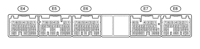
| Symbols (Terminals No.) | Wiring Color | Condition | Specification |
| E1 - Body ground (E6-1 - Body ground) | W-B - Body ground (*3) BR - Body ground (*4) | Always | Below 1.0 V |
| THWO - Body ground (E7-14 - Body ground) | L-B - Body ground | Engine running: Idle speed | Pulse generation (See waveform 2) |
| ACT - Body ground (E7-25 - Body ground) | BR-W - Body ground | Start engine Blower speed: LO Magnetic clutch: Engaged | 10 to 14 V |
| ACT - Body ground (E7-25 - Body ground) | BR-W - Body ground | Start engine Blower speed: LO Magnetic clutch: Not engaged | Below 1.0 V |
| AC1 - Body ground (E7-24 - Body ground) | GR-G - Body ground | Start engine Blower speed: LO Magnetic clutch: Engaged | 10 to 14 V |
| AC1 - Body ground (E7-24 - Body ground) | GR-G - Body ground | Start engine Blower speed: LO Magnetic clutch: Not engaged | Below 1.0 V |
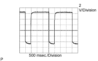 |
Oscilloscope waveform 1:
Terminal to be measured: BLW of A/C amplifier
Setting for measurement: 2 V/DIV, 500 msec./DIV
Condition: Ignition switch ON
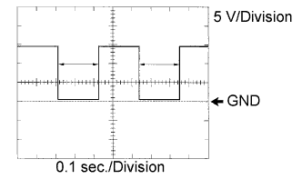 |
Oscilloscope waveform 2:
Terminal to be measured: TWI of A/C amplifier and TWHO of ECM
Setting for measurement: 5 V/DIV, 0.1 sec./DIV
Condition: Ignition switch ON
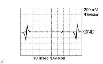 |
Oscilloscope waveform 3:
Terminal to be measured: MGC of A/C amplifier and ECM
Setting for measurement: 200 mV/DIV, 10 msec./DIV
Condition: Ignition switch ON