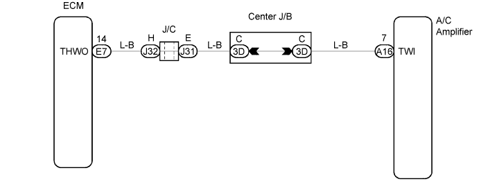
DTC 14 Engine Coolant Temperature Communication Circuit |
| DTC No. | Detection Item | Trouble Area |
| 14 | Open or short in A/C amplifier and ECM circuit |
|
| 1.CHECK DTC |
Check that DTC P0115 is not output.
| Result | Proceed to |
| DTC P0115 is not output. | A |
| DTC P0115 is output. | B |
|
| ||||
| A | |
 |
| 2.INSPECT ECM (THWO) |
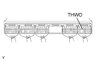 |
Remove the ECM with the connectors still connected.
Turn the ignition switch ON.
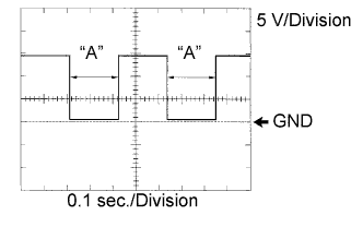 |
Measure the waveform between terminal THWO of the ECM connector and body ground.
| Engine coolant temperature | Frequency "A" |
| Below 30°C (86°F) | 16 ms |
| Approx. 75°C (167°F) | 102 ms |
| 90°C to 100°C (194°F to 212°F) | 262 ms |
|
| ||||
| OK | |
|
| 3.CHECK HARNESS AND CONNECTOR (ECM - AIR CONDITIONING AMPLIFIER) |
Check for open and short circuit in the harness and the connector between the ECM and the A/C amplifier (Click here).
| Result | Proceed to |
| NG | A |
| OK (when checking using PROBLEM SYMPTOMS TABLE) | B |
| OK (when checking using DTC) | B |
|
| ||||
|
| ||||
| A | ||
 | ||
| ||
