Home › HEATER & AIR CONDITIONING SYSTEM › AIR CONDITIONING › AIR CONDITIONING SYSTEM

DTC    21    Solar Sensor Circuit (Passenger Side)

for Preparation Click here


DESCRIPTION

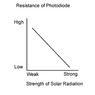
A photodiode in the cooler (solar sensor) thermistor detects solar radiation and sends signals to the A/C amplifier.
E107008E01

DTC No.
Detection Item
Trouble Area
21
Open or short in solar sensor circuit
  1. Cooler (solar sensor) thermistor
  2. Harness or connector between cooler (solar sensor) thermistor and A/C amplifier
  3. A/C amplifier

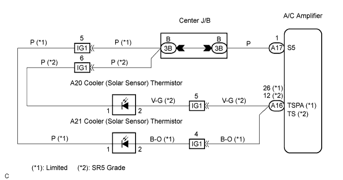
WIRING DIAGRAM


I033596E01


INSPECTION PROCEDURE

HINT:
If the check is performed in a dark place, DTC 21, 24 (solar sensor circuit abnormal) may be output.

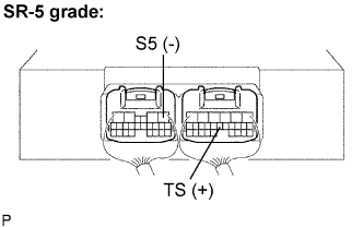
1.INSPECT AIR CONDITIONING AMPLIFIER (TS, TSP, S5)


    I033523E04
  1. Remove the A/C amplifier with the connectors still connected.
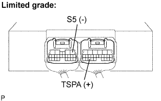


    I033523E05
  1. Measure the voltage according to the value(s) in the table below.

    Standard voltage:
    Tester Connection
    (Symbols)
    Condition
    Specified Condition
    A17-1 (S5) - A16-26 (TSPA) (*1)
    Ignition switch ON
    0.8 to 4.3 V
    A17-1 (S5) - A16-12 (TS) (*2)
    Ignition switch ON
    0.8 to 4.3 V

    *1: Limited
    *2: SR5 Grade

    HINT:
    1. Use an incandescent light for inspection. Bring it within 30 cm (11.8 in.) of the cooler (solar sensor) thermistor.
    2. Move the light away from the sensor voltage increases
    3. Move the light closer to the sensor voltage decreases


OK
PROCEED TO NEXT CIRCUIT INSPECTION SHOWN IN PROBLEM SYMPTOMS TABLE
NG


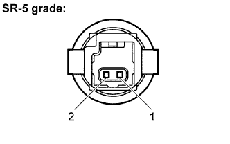
2.INSPECT COOLER (SOLAR SENSOR) THERMISTOR


    I033907E01
  1. Remove the cooler (solar sensor) thermistor.
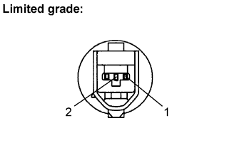


    I033908E01
  1. Measure the resistance according to the value(s) in the table below.

  1. Connect the positive (+) lead from the ohmmeter to terminal 2 and the negative (-) lead to terminal 1 of the cooler (solar sensor) thermistor.

    Standard resistance:
    Tester Connection
    Condition
    Specified Condition
    2 - 1
    Sensor is subject to electric light
    Except ∞ Ω
    2 - 1
    Sensor is covered with a cloth
    ∞ Ω (No continuity)

    NOTICE:
    The connection procedure for using a digital tester such as an electrical tester is shown above. When using an analog tester, connect the negative (-) lead to terminal 2 and positive (+) lead to terminal 1 of the cooler (solar sensor) thermistor.

    HINT:
    1. As the inspection light is moved away from the sensor, the resistance increases.
    2. Use an incandescent light for inspection. Bring it within 30 cm (11.8 in.) of the cooler (solar sensor) thermistor.


NG
REPLACE COOLER (SOLAR SENSOR) THERMISTOR
OK


3.CHECK HARNESS AND CONNECTOR (COOLER (SOLAR SENSOR) THERMISTOR - A/C AMPLIFIER)
  1. Check for open and short circuit in the harness and the connector between the cooler (solar sensor) thermistor and the A/C amplifier (Click here).


NG
REPAIR OR REPLACE HARNESS OR CONNECTOR
OK


4.CHECK DTC
  1. Start up the DTC check mode.

  1. Check that DTC 21 is not output again.

    Result:

    Result
    Proceed to
    DTC 21 is output.
    A
    DTC 21 is not output.
    B


B
SYSTEM IS OK
A

REPLACE AIR CONDITIONING AMPLIFIER