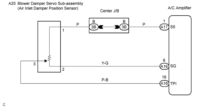
DTC 32 Air Inlet Damper Position Sensor Circuit |
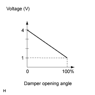
| DTC No. | Detection Item | Trouble Area |
| 32 | Open or short in air inlet damper position sensor circuit |
|
| 1.INSPECT AIR CONDITIONING AMPLIFIER (TPI, SG) |
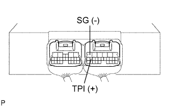 |
Remove the A/C amplifier with the connectors still connected.
Turn the ignition switch ON.
Change the set RECIRCULATION/FRESH to activate the blower damper.
Measure the voltage according to the value(s) in the table below.
| Tester Connection (Symbols) | Condition | Specified Condition |
| A16-16 (TPI) - A16-6 (SG) | Ignition switch ON RECIRCULATION position | 3.5 to 4.5 V |
| A16-16 (TPI) - A16-6 (SG) | Ignition switch ON FRESH position | 0.5 to 1.8 V |
|
| ||||
| NG | |
 |
| 2.INSPECT BLOWER DAMPER SERVO SUB-ASSEMBLY |
Remove the blower damper servo sub-assembly.
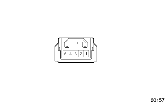 |
Disconnect the connector from the blower damper servo sub-assembly.
Measure the resistance according to the value(s) in the table below.
| Tester Connection | Condition | Specified Condition |
| 1 - 2 | Always | 4.2 to 7.8 kΩ |
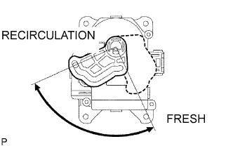 |
Measure the resistance according to the value(s) in the table below.
| Tester Connection | Condition | Specified Condition |
| 3 - 2 | RECIRCULATION position | 0.8 to 1.6 kΩ |
| 3 - 2 | FRESH position | 3.4 to 6.2 kΩ |
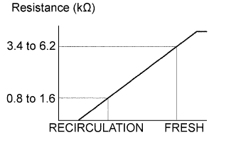 |
As the blower damper servo sub-assembly moves from FRESH side to RECIRCULATION side, the resistance decreases gradually without interruption.
|
| ||||
| OK | |
|
| 3.CHECK HARNESS AND CONNECTOR (AIR INLET DAMPER POSITION SENSOR - A/C AMPLIFIER) |
Check for open and short circuit in the harness and the connector between the blower damper servo sub-assembly (air inlet damper position sensor) and the A/C amplifier (Click here).
|
| ||||
| OK | |
|
| 4.CHECK DTC |
Start up the DTC check mode.
Check that DTC 32 is not output again.
| Result | Proceed to |
| DTC 32 is output. | A |
| DTC 32 is not output. | B |
|
| ||||
| A | ||
 | ||
| ||
