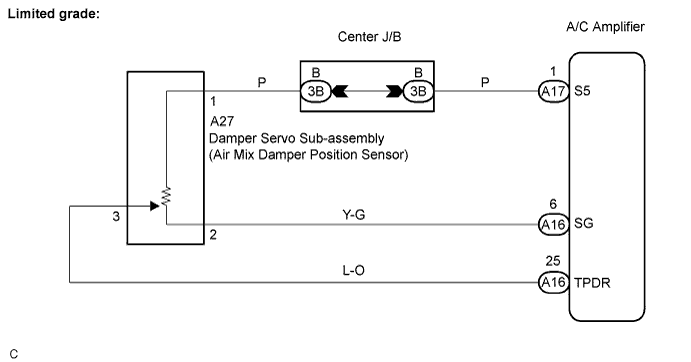
DTC 36 Air Mix Damper Position Sensor Circuit (Driver Side |
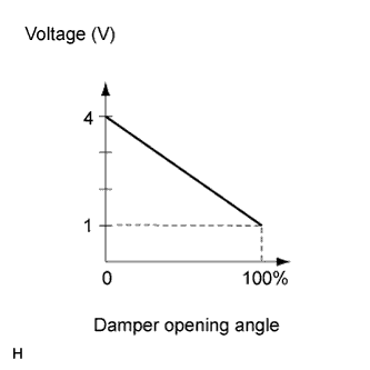
| DTC No. | Detection Item | Trouble Area |
| 36 | Short to ground or power source circuit in air mix damper position sensor circuit |
|
| 1.INSPECT AIR CONDITIONING AMPLIFIER (TPDR, SG) |
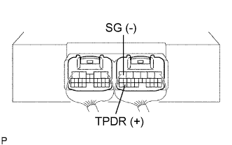 |
Remove the A/C amplifier with the connectors still connected.
Turn the ignition switch ON.
Change the set temperature to activate the air mix damper.
Measure the voltage according to the value(s) in the table below.
| Tester Connection (Symbols) | Condition | Specified Condition |
| A16-25 (TPDR) - A16-6 (SG) | Ignition switch ON MAX. COLD position | 3.5 to 4.5 V |
| A16-25 (TPDR) - A16-6 (SG) | Ignition switch ON MAX. HOT position | 0.5 to 1.8 V |
|
| ||||
| NG | |
 |
| 2.INSPECT DAMPER SERVO SUB-ASSEMBLY |
Remove the damper servo sub-assembly.
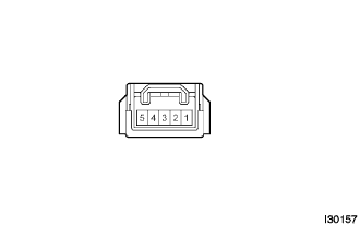 |
Disconnect the connector from the damper servo sub-assembly.
Measure the resistance according to the value(s) in the table below.
| Tester Connection | Condition | Specified Condition |
| 1 - 2 | Always | 4.2 to 7.8 kΩ |
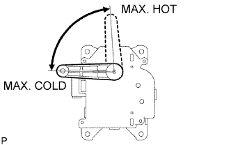 |
Measure the resistance according to the value(s) in the table below.
| Tester Connection | Condition | Specified Condition |
| 3 - 2 | MAX. COLD position | 3.4 to 6.2 kΩ |
| 3 - 2 | MAX. HOT position | 0.8 to 1.6 kΩ |
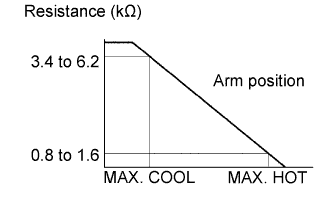 |
As the damper servo sub-assembly moves from COLD side to HOT side, the resistance decreases gradually without interruption.
|
| ||||
| OK | |
|
| 3.CHECK HARNESS AND CONNECTOR (AIR MIX DAMPER POSITION SENSOR - A/C AMPLIFIER) |
Check for open and short circuit in the harness and the connector between the damper servo sub-assembly (air mix damper position sensor) and the A/C amplifier (Click here).
|
| ||||
| OK | |
|
| 4.CHECK DTC |
Start up the DTC check mode.
Check that DTC 36 is not output again.
| Result | Proceed to |
| DTC 36 is output. | A |
| DTC 36 is not output. | B |
|
| ||||
| A | ||
 | ||
| ||
