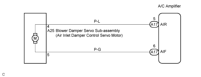
DTC 42 Air Inlet Damper Control Servo Motor Circuit |
| DTC No. | Detection Item | Trouble Area |
| 42 | Air inlet damper position sensor value does not change even if A/C amplifier operates air inlet control servo motor. |
|
| 1.PERFORM ACTUATOR CHECK |
Remove the glove compartment to see and check the recirculation damper operation.
Operate the A/C control panel to enter the actuator check mode (Click here).
Press the DEF switch to enter the step operation.
Press the DEF switch in order, and visually check the recirculation damper operation.
| Display Code | Recirculation damper position |
| 0 | RECIRCULATION |
| 1 | RECIRCULATION |
| 2 | FRESH/RECIRCULATION |
| 3 | FRESH/RECIRCULATION |
| 4 | FRESH |
| 5 | FRESH |
| 6 | FRESH |
| 7 | FRESH |
| 8 | FRESH |
| 9 | FRESH |
|
| ||||
| NG | |
 |
| 2.INSPECT BLOWER DAMPER SERVO SUB-ASSEMBLY |
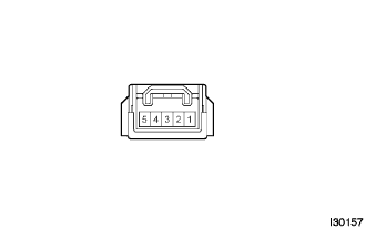 |
Remove the blower damper servo sub-assembly.
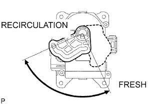 |
Connect the battery positive (+) lead to terminal 4 and the battery negative (-) lead to terminal 5, then check that the lever turns to "RECIRCULATION" side smoothly.
Connect the battery positive (+) lead to terminal 5 and the battery negative (-) lead to terminal 4, then check that the lever turns to "FRESH" side smoothly.
|
| ||||
| OK | |
|
| 3.CHECK HARNESS AND CONNECTOR (BLOWER DAMPER SERVO SUB-ASSEMBLY - A/C AMPLIFIER) |
Check for open and short circuit in the harness and the connector between the blower damper servo sub-assembly (air inlet damper control servo motor) and the A/C amplifier (Click here).
|
| ||||
| OK | |
|
| 4.CHECK DTC |
Start up the DTC check mode.
Check that DTC 42 is not output again.
| Result | Proceed to |
| DTC 42 is output. | A |
| DTC 42 is not output. | B |
|
| ||||
| A | ||
 | ||
| ||
