 |
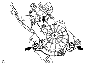
Install the 3 insulators to the air pump assembly.
AIR PUMP > INSTALLATION |
| 1. INSTALL AIR PUMP ASSEMBLY |
|
Install the 3 insulators to the air pump assembly.
Install the air pump assembly with the 3 bolts.
| 2. INSTALL AIR PUMP ASSEMBLY WITH BRACKET |
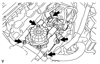 |
Install the air pump assembly with the 4 bolts.
Connect the pressure sensor connector for the air injection system.
Connect the air switching valve connector.
Connect the No. 2 air hose to the air switching valve.
| 3. INSTALL WATER BY-PASS PIPE SUB-ASSEMBLY |
Install a new O-ring to the water by-pass pipe.
Apply soapy water to the O-ring.
Push in the water by-pass pipe end into the pipe hole of the water pump.
Install the water by-pass pipe with the bolt.
| 4. INSTALL INTAKE MANIFOLD ASSEMBLY |
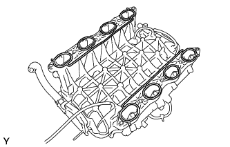 |
Place 2 new gaskets on the intake manifold.
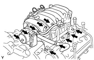 |
Place the intake manifold on the cylinder heads.
Install and uniformly tighten the 6 bolts and 4 nuts in several steps.
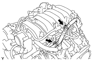 |
Install the V-bank cover bracket to the intake manifold.
Install the wire bracket to the intake manifold with the bolt.
Connect the engine wire to the engine hanger and wire bracket.
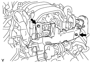 |
Connect the wire protector to the intake manifold and cylinder heads with the bolt and nut.
Install the 2 ground cables with the 2 bolts to the RH and LH cylinder heads.
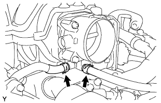 |
Connect the 2 water by-pass hoses to the throttle body.
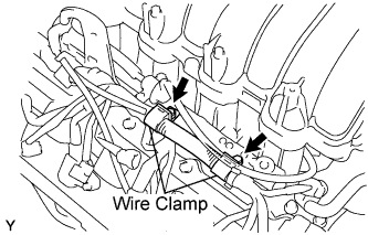 |
Connect the 2 wire clamps to the wire clamp bracket on the RH delivery pipe.
| 5. CONNECT HOSES FROM INTAKE MANIFOLD |
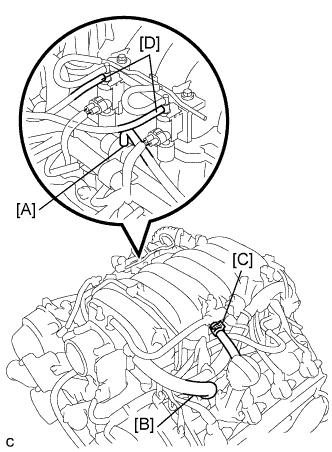 |
Connect the vacuum hose [A] to the fuel pressure regulator.
Connect the PCV hose [B] to the PCV valve on the LH cylinder head.
Connect the EVAP hose (from the charcoal canister) [C] to the VSV for EVAP.
Connect the 2 vacuum hoses [D] to the VSV for the air injection system.
| 6. CONNECT CONNECTORS FROM INTAKE MANIFOLD |
Connect the throttle control connector.
Connect the 2 VSV connectors for the air injection system.
Connect the VSV connector for the EVAP.
Connect the 8 injector connectors.
Connect the ECT sensor connector.
Connect the 8 ignition coil connectors.
Connect the 2 air fuel ratio sensor connectors.
| 7. INSTALL FUEL NO. 2 HOSE |
| 8. INSTALL FUEL HOSE |
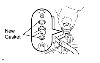 |
Using 2 new gaskets, install the fuel main hose with the fuel pressure pulsation damper.
| 9. INSTALL AIR CLEANER HOSE ASSEMBLY |
| 10. INSTALL THROTTLE BODY COVER SUB-ASSEMBLY |
Install the throttle body cover sub-assembly with the 2 nuts.
| 11. ADD ENGINE COOLANT |
Slowly fill the system with engine coolant.
Install the radiator cap securely.
Bleed the cooling system.
Open the heater water valve while warming up the engine.
Maintain the engine speed at 2,000 to 2,500 rpm and warm up the engine.
Stop the engine and wait until the coolant cools down.
Add coolant into the reservoir until the coolant level is FULL.
| 12. CHECK FOR ENGINE COOLANT LEAKS |
Fill the radiator with coolant and attach a radiator cap tester.
Pump it to 118 kPa (1.2 kgf/cm2 17.1 psi), then check for leakage.
| 13. CHECK FOR FUEL LEAKS |
When using the intelligent tester
Connect the intelligent tester to the DLC3.
Turn the ignition switch ON and intelligent tester main switch ON.
Select the ACTIVE TEST mode on the intelligent tester.
Please refer to the intelligent tester operator's manual for further details.
 |
When not using the intelligent tester
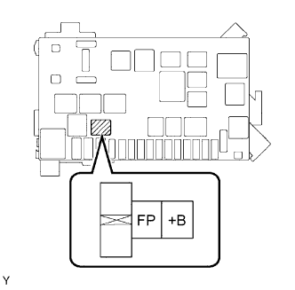
Remove the circuit opening relay.
Using a service wire, connect terminals FP and +B of the relay block.
Turn the ignition switch ON, and check that the fuel pump operates.
Check that there are no fuel leaks after doing maintenance anywhere on the fuel system.
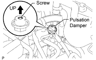 |
Check that the pulsation damper screw rises up when the fuel pump operates.
If operation is not as specified, check the following parts:
Turn the ignition switch OFF.
Disconnect the intelligent tester from the DLC3.