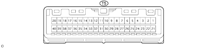
THEFT DETERRENT SYSTEM > TERMINALS OF ECU |
| CHECK THEFT WARNING ECU ASSEMBLY (THEFT DETERRENT ECU) |
Disconnect the T5 ECU connector, and check the voltage or continuity between each terminal of the wire harness side connector.
| Symbols (Terminal No.) | Wiring Color | Condition | Specified Condition |
| E (T5-29) - Body ground | W-B - Body ground | Always | Below 1 Ω |
| +B2 (T5-3) - E (T5-29) | W-L - W-B | Always | 10 to 14 V |
| IG (T5-10) - E (T5-29) | B-R - W-B | Ignition switch OFF to ON | Below 1 V → 10 to 14 V |
| +B1 (T5-2) - E (T5-29) | W-R - W-B | Always | 10 to 14 V |
Reconnect the T5 ECU connector, and check the voltage between each terminal of the connector.
| Symbols (Terminal No.) | Wiring Color | Condition | Specified Condition |
| IND (T5-25) - E (T5-29) | GR-G - W-B | Security indicator light lights up. (It lights up only for 30 sec. in alarming sounding state. It flashes when immobiliser system is operating) | 3 to 6 V |
| SH- (T5-1) - E (T5-29) | BR-B - W-B | Security horn is sounding. (Theft deterrent system is in alarming sounding state) | 10 to 14 V |
| CHECK INSTRUMENT PANEL JUNCTION BLOCK ASSEMBLY (BODY ECU) |
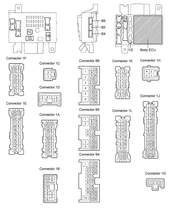
Disconnect the J/B connector, and check the voltage or continuity between each terminal of the wire harness side connector.
| Symbols (Terminal No.) | Wiring Color | Condition | Specified Condition |
| BDR1 (1E-9) - Body ground | G-W - Body ground | Always | 10 to 14 V |
| GND1 (1H-2) - Body ground | W-B - Body ground | Always | Below 1 Ω |
| GND2 (1H-2) - Body ground | W-B - Body ground | Always | Below 1 Ω |
| KSW (B6-14) - Body ground | G-Y - Body ground | No key in ignition key cylinder → Key inserted | 10 kΩ or higher → Below 1 Ω |
Reconnect the J/B connector, and check the voltage between each terminal of the connector.
| Symbols (Terminal No.) | Wiring Color | Condition | Specified Condition |
| DCTY (B5-23) - Body ground | R-B - Body ground | Driver side door CLOSED → OPEN | 10 to 14 V → Below 1 V |
| PCTY (B5-24) - Body ground | R-Y - Body ground | Passenger side door CLOSED → OPEN | 10 to 14 V → Below 1 V |
| RLCY (B5-11) - Body ground | P-B - Body ground | Rear door LH CLOSED → OPEN | 10 to 14 V → Below 1 V |
| RRCY (B5-12) - Body ground | P-L - Body ground | Rear door RH CLOSED → OPEN | 10 to 14 V → Below 1 V |
| ACT+ (1L-9) - Body ground | L-R - Body ground | Master switch and driver side door key cylinder OFF → LOCK | Below 1 V → 10 to 14 V |
| ACT- (1L-18) - Body ground | L-B - Body ground | Master switch and driver side door key cylinder OFF → UNLOCK | Below 1 V → 10 to 14 V |
| INSPECT MULTIPLEX NETWORK DOOR ECU BACK (BACK DOOR ECU) |

Disconnect the B8 ECU connector, and check the voltage of each terminal of the wire harness side connector.
| Symbols (Terminal No.) | Wiring Color | Condition | Specified Condition |
| BDR (B8-4) - Body ground | L - Body ground | Always | 10 to 14 V |
| BECU (B8-5) - Body ground | L-R - Body ground | Always | 10 to 14 V |
| GND (B8-3) - Body ground | W-B - Body ground | Ignition switch OFF → ON | Below 1 V → 10 to 14 V |
Reconnect the B8 ECU connector, and check the voltage of each terminal of the connector.
| Symbols (Terminal No.) | Wiring Color | Condition | Specified Condition |
| ACT+ (B9-15) - Body ground | L-B - Body ground | Back door OPEN → NOT COMPLETELY CLOSED → Monitor in normal rotation (Right turn) → Motor in reverse rotation (left turn) → Operation completed (Back door CLOSED) | Below 1 V → Below 1 V → 10 to 14 V → Below 1 V → Below 1 V |
| ACT- (B9-14) - Body ground | L-R - Body ground | Back door OPEN → NOT COMPLETELY CLOSED → Monitor in normal rotation (Right turn) → Motor in reverse rotation (left turn) → Operation completed (Back door CLOSED) | Below 1 V → Below 1 V → Below 1 V → 10 to 14 V → Below 1 V |